Description
Shinkawa VM-703B/NB1/CS1/TRP/TB1 Tachometer & Eccentricity Monitor
Product Overview
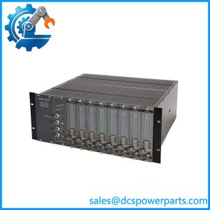
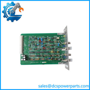
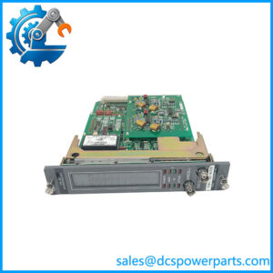
The Shinkawa VM-703B/NB1/CS1/TRP/TB1 is a specialized rotating-machinery monitoring module in the VM-7 monitoring system. Its primary job is not generic PLC signal processing; it continuously evaluates rotor speed and eccentricity for large rotating equipment such as turbines, generators, compressors, and other critical machinery. The VM-703B provides two tachometer channels and one eccentricity channel, with the tachometer section supporting proximity transducers or magnetic pickups and the eccentricity channel supporting specified proximity-probe configurations. Shinkawa identifies the VM-703B as its Tachometer & Eccentricity Monitor Module.
The suffixes are important here. /NB1 identifies the non-incendive CSA C/US Class I, Division 2, Groups A, B, C and D configuration; /CS1 specifies a custom monitor setup; /TRP identifies the tropical specification; and /TB1 supplies the specified transducer, recorder-output, and contact-output terminal-block plugs. Shinkawa’s specification assigns /TB1 to the VM-761B instrument-rack arrangement.
In operation, the VM-703B/NB1/CS1/TRP/TB1 can generate speed alarms, eccentricity alarms, buffered monitor outputs, pulse outputs, and recorder signals. The six relay contacts are individually associated with alarm functions according to the configured setup. This makes the module suitable for turbine supervisory instrumentation and rotating-equipment protection schemes where speed and shaft eccentricity need to remain visible even when the main control system is handling other process functions.
Product Introduction
Rotor-speed monitoring is not the same task as speed control. The VM-703B is deliberately designed as a monitoring device: Shinkawa explicitly cautions that its VM-5 and VM-7 speed monitors are intended for monitoring rather than controlling rotational speed. Its relay and 4–20 mA recorder outputs should therefore be treated as alarm/recording signals, not governor commands.
For a legacy turbine or compressor system, the complete suffix matters. This particular unit combines custom setup, tropical specification, non-incendive Class I Division 2 construction, and /TB1 terminal accessories. Replacing it with a plain VM-703B can therefore remove application-specific configuration or create a field-wiring mismatch.
Key Technical Specifications
| Parameter | Specification |
|---|---|
| Manufacturer | Shinkawa Electric |
| Model | VM-703B/NB1/CS1/TRP/TB1 |
| Product Family | VM-7 Monitoring System |
| Product Type | Tachometer & Eccentricity Monitor Module |
| Tachometer Inputs | 2 |
| Eccentricity Input | 1 |
| Tachometer Input Impedance | Approx. 50 kΩ; approx. 5 kΩ for magnetic pickup input |
| Maximum Input Voltage | 100 Vp-p |
| Tachometer Frequency Range | 0.01 Hz to 10 kHz |
| Minimum Tachometer Pulse Width | 50 μs |
| Tachometer Monitor Range | 0–5000 rpm in documented standard setup |
| Input Pulses | 1–200 pulses/rev for rotor-speed monitoring |
| Rotor-Speed Accuracy | ±(0.003% of reading + 1 digit) at 25°C |
| Rotor-Speed Accuracy, 0–65°C | ±(0.03% of reading + 1 digit) |
| Eccentricity P-P Range | 1–300 rpm or 1–600 rpm measurement basis; 0–100 μm documented setup |
| Eccentricity Direct Range | ±50 μm |
| Recorder Outputs | 4 |
| Recorder Output Ranges | 1–5 V, 4–20 mA, 0–5 V, 0–10 V |
| Recorder Accuracy | ±1% FS at 25°C; ±2% FS at 0–65°C |
| Maximum Current-Mode Load | 600 Ω |
| Relay Outputs | 6 |
| Relay Contact | SPDT dry contact |
| Relay Rating | 250 VAC / 5 A; 30 VDC / 5 A |
| Speed Relay Setpoints | 4 points: HH, H, L, LL |
| Speed Relay Mode | Overspeed / underspeed |
| Speed Relay Hysteresis | 0–100 rpm, 1 rpm steps |
| Eccentricity Alarm Setpoints | Alert / Danger and high/low direct-monitoring thresholds |
| Alarm Delay | 0–99 seconds, 0.1-second steps |
| Proximity Transducer Supply | -24 VDC / 25 mA maximum |
| Operating Temperature | 0 to +65°C |
| Explosion-Proof/Non-Incendive Operating Temperature | 0 to +60°C |
| Storage Temperature | -30 to +85°C |
| Relative Humidity | 20–95% RH, non-condensing |
| Module Power Consumption | Less than 15 W |
| Module Mass | Maximum 1.0 kg |
| /NB1 | CSA C/US Class I, Division 2, Groups A, B, C and D |
| /CS1 | Custom monitor-function setup |
| /TRP | Tropical specification |
| /TB1 | Terminal-block accessory package |
The specifications above are taken from Shinkawa’s VM-703B specification sheet. Some values, such as the 0–5000 rpm range and 0–100 μm eccentricity configuration, are identified in the document as a particular setup rather than universal limits for every possible VM-703B configuration.
Major Features / Practical Advantages
Dual tachometer channels
The VM-703B provides two independent tachometer inputs. Shinkawa specifies compatibility with FK-202F and RD-05A proximity transducers, as well as MS-160 and MS-240 magnetic pickups for the first two channels.
Two channels also allow the module to determine rotational direction when properly installed against a toothed target. The sensor phase relationship is not arbitrary. Shinkawa specifies a relationship between the number of gear teeth and the sensor angle, and the two pulse trains must overlap appropriately for direction determination.
That is a commissioning detail worth taking seriously. If the probes are mechanically installed at the wrong phase angle, the electronics may be perfectly healthy while reverse-rotation detection remains incorrect.
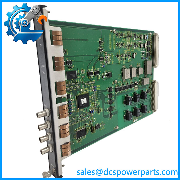
VM-703B/NB1/CS1/TRP/TB1
Eccentricity measurement
Channel 3 is dedicated to eccentricity measurement. Supported probe families include FK-202F, FK-302F, VK-202A, VK-202P, VK-302P and VC-020 configurations.
The module supports both peak-to-peak eccentricity monitoring and direct eccentricity monitoring. In the documented configuration, peak-to-peak monitoring uses a 0–100 μm range, while direct monitoring uses a -50 to +50 μm range. Accuracy is specified as ±1% of full scale at 25°C and ±2% over 0–65°C.
For steam turbines and other large rotating machinery, this is a fundamentally different measurement from ordinary vibration amplitude. Shaft eccentricity indicates geometric movement of the rotor relative to the measurement reference and can become important during startup, shutdown, and low-speed conditions.
Four recorder outputs
The VM-703B provides four recorder outputs that can be assigned to measured values from the module. Available output formats include 1–5 V, 4–20 mA, 0–5 V, and 0–10 V. Current-mode load resistance is specified up to 600 Ω.
This makes the module straightforward to integrate with a plant historian, PLC analog input, DCS input card, or standalone recorder, provided the signal range and grounding arrangement are engineered correctly.
Six configurable alarm contacts
Six SPDT dry-contact relays are available. The relay logic can be changed between normally energized and normally de-energized field configurations. Contact capacity is specified at 250 VAC/5 A or 30 VDC/5 A.
The documented default configuration assigns four contacts to tachometer speed thresholds—HH, H, L and LL—and two contacts to eccentricity Danger and Alert conditions. Because the unit carries /CS1 custom setup, the actual installed relay assignment should be confirmed from the system configuration rather than assumed from the default table.
High-resolution tachometer measurement
The tachometer input supports frequencies from 0.01 Hz through 10 kHz, with a minimum pulse width of 50 μs. Rotor-speed accuracy is specified at ±(0.003% of reading + 1 digit) at 25°C.
The 0.01 Hz lower measurement limit is particularly relevant at low rotational speeds. With the number of gear teeth and pulse-per-revolution ratio known, the minimum measurable rotor speed can be calculated from the frequency limit rather than guessed from the nominal rpm range.
Non-incendive Class I Division 2 configuration
The /NB1 suffix is not decorative. Shinkawa identifies it as the non-incendive version with CSA C/US Class I, Division 2, Groups A, B, C and D classification.
That makes the exact suffix important for hazardous-location procurement. A plain VM-703B should not automatically be treated as equivalent to the /NB1 configuration.
Tropical specification
The /TRP suffix identifies the tropical specification. The base specification gives 20–95% RH non-condensing and an operating range of 0–65°C, with the explosion-proof/non-incendive construction specified separately at 0–60°C.
For replacement procurement, retaining /TRP is preferable when the original equipment was specified for tropical environmental conditions. Do not assume that an ordinary VM-703B has identical environmental qualification.
/TB1 terminal accessory package
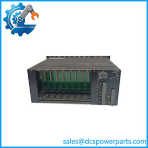
The /TB1 option includes the terminal-block plugs required for the documented VM-761B rack arrangement: the 15-pin transducer input plug, recorder-output plugs, and 18-pin contact-output plug. Shinkawa specifically notes that the D-sub plug and hood for the monitor-output connector are not included with /TB1.
That is a small procurement detail with practical consequences. If a replacement is being purchased as a complete service spare, check whether the required D-sub hardware is already available in the cabinet.
Related Products
- VM-701B — VM-7 vibration/displacement monitor for shaft vibration and displacement measurements; functionally different from the VM-703B speed/eccentricity module.
- VM-702B — VM-7 absolute vibration monitor for absolute vibration measurements.
- VM-704B — VM-7 temperature monitor for rotating-equipment temperature measurements.
- VM-706B — VM-7 rod-drop monitor for reciprocating machinery applications.
- VM-741B — Local Communication & Phase Marker Module; can provide phase-marker inputs to the VM-703B through the internal motherboard.
- VM-742B — Network Communication Module for VM-7 system communications.
- VM-721B — 18-channel relay module for expanding VM-7 alarm/contact functionality.
- VM-751B — Primary power-supply module for the VM-7 rack.
- VM-752B — Secondary power-supply module for redundant VM-7 rack power.
- VM-761B — Instrument rack specifically identified by the VM-703B /TB1 accessory documentation.
FAQ
What is the Shinkawa VM-703B/NB1/CS1/TRP/TB1 used for?
It is a tachometer and eccentricity monitoring module in the Shinkawa VM-7 monitoring system. It monitors two speed inputs and one eccentricity input and provides analog recorder outputs plus relay alarm contacts.
Is this a vibration monitor?
Not primarily. The VM-703B is specifically the Tachometer & Eccentricity Monitor Module. The VM-701B and VM-702B handle other vibration/displacement monitoring functions in the same VM-7 system.
Can I use the VM-703B to control turbine speed?
No. Shinkawa explicitly states that its VM-5 and VM-7 rotational-speed monitors are designed for monitoring rather than rotational-speed control. The speed relay and 4–20 mA recorder outputs should be used for alarm and recording purposes, not as governor-control commands.
Can I hot-swap this module?
Do not assume unrestricted hot swapping merely because the module is rack-mounted. The VM-7 architecture uses plug-in monitor modules, but maintenance should follow the applicable Shinkawa rack procedure and plant isolation requirements. A turbine supervisory instrument should not be removed from an energized protection circuit without confirming the effect on alarm and trip logic.
What does /NB1 mean?
/NB1 identifies the non-incendive version with CSA C/US Class I, Division 2, Groups A, B, C and D classification in the Shinkawa specification.
What does /CS1 mean?
/CS1 identifies the custom setup configuration. The actual alarm thresholds, relay assignments, measurement ranges and related parameters should therefore be checked against the installed configuration rather than assumed from the base VM-703B model.
What does /TRP mean?
/TRP denotes the tropical specification. The manufacturer’s environmental specification includes 20–95% RH non-condensing and 0–65°C normal operating temperature, with 0–60°C specified for the non-incendive/explosion-proof construction.
What does /TB1 include?
The /TB1 accessory package includes the transducer-input, recorder-output, and contact-output terminal-block plugs for the VM-761B rack arrangement. Shinkawa states that the D-sub plug and hood for the monitor-output connection are not included under /TB1.
Does it support firmware v3.1?
A specific firmware version such as v3.1 should not be assigned to this part number without the applicable VM-7/infiSYS documentation. The manufacturer’s VM-703B specification does note that some functions may not be available on older versions, so version history can matter during a legacy replacement.
What sensors can be connected?
For tachometer channels 1 and 2, Shinkawa specifies FK-202F and RD-05A proximity transducers and MS-160/MS-240 magnetic pickups. The eccentricity channel supports FK-202F, FK-302F, VK-202A, VK-202P, VK-302P and VC-020 configurations.
Is a New Surplus VM-703B/NB1/CS1/TRP/TB1 equivalent to a standard VM-703B?
No. The suffix configuration carries real engineering significance. /NB1 provides the documented hazardous-location construction, /CS1 indicates custom setup, /TRP specifies tropical construction, and /TB1 identifies the terminal accessory package. A bare VM-703B should not be assumed to reproduce all four characteristics.
Procurement Note
For Shinkawa VM-703B/NB1/CS1/TRP/TB1, the complete ordering code should be treated as the product identity. Buying a generic VM-703B and assuming the suffixes are optional can create three separate problems: hazardous-location compliance, configuration mismatch, and missing field connectors.
The most important checks are:
VM-703B → /NB1 → /CS1 → /TRP → /TB1 → host rack model → sensor type → configured alarm thresholds.
The manufacturer’s documentation confirms that /NB1 is the Class I Division 2 non-incendive configuration, /CS1 is a custom setup, /TRP is the tropical specification, and /TB1 supplies the specified terminal-block plugs.
For the /TB1 version specifically, verify whether the existing installation uses the VM-761B rack and whether the D-sub monitor-output plug is already installed or needs to be procured separately. Shinkawa’s documentation explicitly states that the D-sub plug and hood are not included in the /TB1 accessory code.
Before approving a replacement for turbine or compressor service, request:
Exact model code → physical nameplate → hardware/revision identification → VM-761B/762B rack confirmation → sensor model → custom configuration record → relay logic → alarm setpoints → functional test evidence.
One final field point: do not confuse the VM-703B with a speed controller. Shinkawa itself defines the VM-7 rotational-speed monitors as monitoring instruments, with the speed relay and recorder outputs intended for alarm and recording functions.