Description
Product Overview
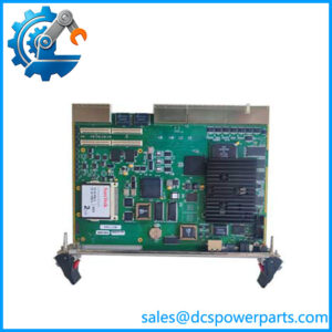
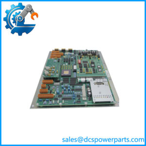
The Rolls-Royce WRC1021D is a dedicated remote controller board used in marine machinery control applications where an operator command must be compared against mechanical feedback and converted into controlled hydraulic servo action. Documentation identifies the WRC1021D as a replacement for the earlier WRC1021 board while retaining mechanical and functional compatibility with that design. Its control logic centers on the difference between an order signal and feedback potentiometer signal. When the two signals are not balanced, the board drives the appropriate servo-valve output; once the commanded position is reached, the valve outputs become inactive and hold the achieved position.
In practical marine automation, the Rolls-Royce WRC1021D can sit between operator command circuitry, feedback devices, and hydraulic valve actuation associated with deck machinery or winch functions. The controller can handle main and slave order inputs, with configurable functions for hoist, lower, bypass, and limit-alarm conditions. One useful protection feature is the bypass response when the order remains in neutral for approximately seven seconds, provided that option has not been disabled. This makes the board a control element rather than a general-purpose PLC I/O module.
From a procurement standpoint, the electrical interface deserves careful checking. The documented supply arrangements include 230 VAC at 50–60 Hz and 24 VDC, while the maximum servo-driver output is specified at 1.5 A at 220 VAC and limit-alarm outputs are rated up to 2.0 A at 24 VDC. The board uses a 100 × 160 mm Euro Card format and weighs approximately 385 grams. For a legacy replacement, these values matter more than a generic description such as “marine controller.” Confirm the board revision, serial number, feedback potentiometer arrangement, DIP-switch configuration, and actual vessel control-system documentation before commissioning a replacement.
Product Introduction
A servo valve cannot simply be driven from a command signal and expected to hold the required position. The Rolls-Royce WRC1021D closes that control loop by comparing order and feedback signals, then commanding the relevant hoist, lower, or bypass valve output.
With a documented 100 × 160 mm Euro Card footprint and support for 230 VAC or 24 VDC supply arrangements, it is suited to legacy marine deck-machinery control systems where board-level replacement is preferable to redesigning the complete control cabinet.
Key Technical Specifications
| Parameter | Value |
|---|---|
| Product Model | WRC1021D |
| Manufacturer / Brand | Rolls-Royce |
| Product Type | Remote Controller / Servo-Valve Control Board |
| Application | Marine deck machinery and winch control |
| Functional Principle | Order-versus-feedback servo control |
| Power Supply | 230 VAC, 50–60 Hz / 24 VDC |
| 230 VAC Consumption | Approx. 0.04 A without servo valves connected |
| 24 VDC Consumption | Up to 4.0 A, depending on output-limit alarm configuration |
| Maximum Servo Driver Output | 1.5 A at 220 VAC |
| Maximum Limit Alarm Output | 2.0 A at 24 VDC |
| Board Format | 100 × 160 mm Euro Card |
| Weight | Approx. 385 g |
| Main Controlled Functions | Hoist, lower, bypass |
| Order Inputs | Main order and optional slave order |
| Feedback | Feedback potentiometer |
| Neutral Bypass Function | Approximately 7 seconds, when enabled |
| Status Indication | Power, operation, valve and alarm indications |
| Compatibility Position | Replacement for earlier WRC1021 design |
| Condition | New Surplus — verify actual unit condition and revision |
The documented electrical ratings above come from the WRC1021D controller instructions. Some secondary listings give conflicting environmental, enclosure, and communication specifications; those values should not be treated as confirmed specifications without the vessel-specific documentation.
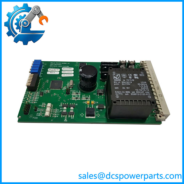
WRC1021D
Related Products
- WRC1021 — The earlier controller design that was developed to replace. It is relevant when maintaining legacy installations and comparing original board configurations.
- WRC1021B — A related WRC controller designation referenced in the calibration documentation. Configuration and revision should be checked before treating it as interchangeable with .
- WRC1024D — A related controller designation appearing in the WRC documentation. Its application and electrical configuration should be verified against the installed system rather than assuming direct substitution.
- WRC121A — A related marine controller board referenced by secondary product information. It should be treated as a different board unless the original Rolls-Royce control-system documentation confirms functional interchangeability.
- Feedback Potentiometer Assembly — The depends on feedback from the controlled mechanism. A faulty or incorrectly calibrated feedback potentiometer can produce symptoms that appear to be controller failure.
- Servo Valve Assembly — The drives the associated servo-valve circuitry. Valve condition, wiring, and coil ratings should be checked before condemning the controller.
- Limit Alarm Circuitry — The controller provides limit-alarm outputs as part of the control arrangement. These circuits should be checked when troubleshooting output-limit or operating-range faults.
Frequently Asked Questions
1. What does the Rolls-Royce actually control?
The is a closed-loop remote controller for marine machinery. It compares an operator’s order signal with a feedback signal and adjusts servo-valve outputs according to the difference.
Typical functions include:
- Hoist control
- Lower control
- Bypass operation
- Main and optional slave order processing
- Limit-alarm handling
- Feedback-based position control
The board therefore belongs to the machine-control layer rather than being a conventional PLC CPU or general-purpose remote I/O module.
2. Can I replace an older WRC1021 directly with ?
The available documentation specifically describes the D version as a replacement for the older WRC1021 and states that it is mechanically and functionally compatible with that earlier design.
For an actual vessel installation, verify:
- Existing WRC board part number and revision.
- Supply voltage used by the cabinet.
- Servo-valve wiring and load.
- Feedback potentiometer arrangement.
- DIP-switch and option settings.
- Existing calibration values.
The documented compatibility is strong evidence for the intended replacement relationship, but site-specific wiring still needs to be checked.
3. Can I hot-swap the ?
Do not treat the as a hot-swappable PLC module.
Because it can control servo-valve outputs and associated hydraulic machinery, replacement should normally be performed with the controlled equipment placed in the appropriate safe state and the relevant electrical and hydraulic energy isolated according to the vessel’s approved maintenance procedure.
A board that can be physically removed from a rack is not automatically safe to remove under power.
4. What power supply does require?
The controller documentation specifies two supply arrangements:
- 230 VAC, 50–60 Hz
- 24 VDC
The documented consumption is approximately 0.04 A at the 230 VAC supply when servo valves are not connected, while the 24 VDC configuration can reach 4.0 A depending on the output-limit alarm configuration.
Do not select the replacement based only on the nominal “24 VDC” description found in secondary listings. Check the actual cabinet wiring and controller documentation.
5. How do I calibrate after replacement?
Calibration is not simply a matter of installing the card and applying power. The controller uses feedback potentiometer information to establish the relationship between command position and the controlled mechanism.
A typical commissioning sequence involves:
- Confirming the hydraulic system is in the required maintenance condition.
- Checking the control lever’s neutral position.
- Checking the feedback potentiometer.
- Applying the specified calibration procedure.
- Moving the control through the required hoist and lower positions.
- Verifying valve response and neutral behavior.
- Confirming limit-alarm operation.
The manufacturer’s controller instructions should be followed for the exact adjustment sequence.
6. Will replacing erase my PLC or control-system logic?
The is a dedicated controller board rather than a conventional programmable PLC CPU. Its operating behavior is established through its hardware circuitry, potentiometers, switches, options, and connected feedback/control signals.
Replacing the board therefore does not correspond to downloading a PLC program into a new CPU. However, the replacement must be configured and calibrated to match the installed machinery. Incorrect switch positions or feedback calibration can cause incorrect valve behavior even when the replacement board itself is functional.
7. How should I verify a New Surplus before installation?
For a critical marine spare, inspect the board before connecting it to the vessel system.
Recommended incoming inspection includes:
- Verify identification.
- Record the serial number and product revision.
- Inspect the PCB and connectors for corrosion, contamination, or mechanical damage.
- Confirm the supply configuration against the vessel’s existing installation.
- Compare connector locations and board dimensions.
- Check potentiometer and switch positions against the original board.
- Confirm the servo-valve load is within the documented output rating.
- Perform controlled bench testing where appropriate.
- Document the inspection results before commissioning.
“New surplus” should describe the physical supply condition, not substitute for electrical testing or traceability. For a board installed in a vessel’s control system, inspection records are worth keeping with the spare.