Description
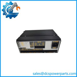
Parker GV6-U12 ENK-13669 | Gemini Digital Servo Drive | 12A Motion Controller
Key Technical Specifications
| Parameter | Specification |
|---|---|
| Manufacturer | Parker Compumotor / Parker Hannifin |
| Model | GV6-U12 ENK-13669 |
| Part Number | GV6-U12 ENK-13669 |
| Product Family | Gemini GV6 |
| Product Type | Digital Servo Drive / Controller |
| AC Input | 95–264 VAC, 1-phase, 50/60 Hz |
| Continuous Output Current | 12 A peak at 8 kHz |
| Peak Output Current | 30 A peak |
| Continuous Output Power | 3.5 kW maximum |
| Peak Output Power | 8.8 kW maximum |
| PWM Frequency | 8, 16, or 20 kHz on U12-class hardware |
| Control Modes | Torque, velocity, step/direction, CW/CCW, encoder tracking |
| Serial Interface | RS-232/RS-485 |
| Keep-Alive Supply | Optional 19.2–28.8 VDC |
| Motion Functions | Registration, motion profiles, S-curve profiling, programmable logic |
| Protection | Overcurrent, short circuit, overvoltage, undervoltage/brownout, thermal and regeneration protection |
Parker’s GV6 hardware documentation specifies the U12 input range as 95–264 VAC single-phase and gives the U12 output capability as 12 A continuous and 30 A peak, with approximately 3.5 kW continuous and 8.8 kW peak power at the stated operating conditions. The same documentation identifies selectable PWM frequencies for the U12 family.
Product Introduction
The Parker is a Gemini GV6 digital servo drive/controller intended for closed-loop industrial motion control. Unlike a basic servo amplifier, the GV6 platform combines drive electronics with programmable motion-control functions, allowing the unit to execute motion profiles, registration operations, velocity shaping, conditional logic, and other machine-control tasks. Parker documentation identifies the GV6 as a ±10 V servo drive/controller family with programmable capabilities.
The Parker belongs to the U12 power class, supporting 95–264 VAC single-phase input and up to 12 A continuous output current with 30 A peak capability. The exact suffix remains important because GV6 configuration codes distinguish drive characteristics such as feedback type and other options.
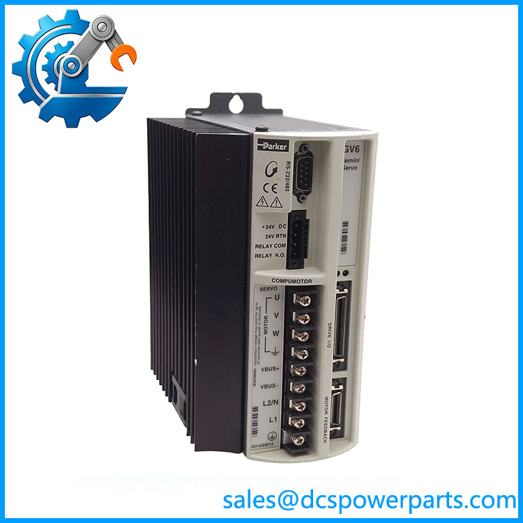
GV6U12 ENK-13669
Application Scenarios & Field Pitfalls — The Engineer’s Perspective
Engineering Pain Point
When a legacy servo machine loses its axis, replacing the drive with another unit from the same GV6 family is not enough. The motor feedback device, command interface, firmware, tuning parameters, motion program, power rating, and machine-specific I/O configuration all affect whether the replacement will actually run the axis correctly.
Typical Applications
1. Precision machine axes
The GV6 can provide closed-loop servo control for positioning systems requiring controlled velocity, torque, and position behavior.
2. Automated production machinery
Its integrated motion-control functions are suited to machines requiring registration, programmed profiles, synchronized movement, and conditional sequences.
3. Material handling and indexing equipment
The drive/controller architecture can handle repeatable positioning and coordinated machine movements without requiring a separate motion controller for every application.
4. Legacy servo-system maintenance
The remains relevant when an existing machine depends on the Gemini GV6 platform and a direct functional replacement is preferable to a complete controls retrofit.
Technical Pitfalls
Confirm the complete configuration code.
GV6 products use model information that identifies the basic drive family, power level, and feedback arrangement. Parker’s programming reference shows, for example, that GV6 feedback options include encoder and resolver configurations. Do not substitute an encoder version for a resolver-equipped machine without confirming the application.
Do not assume is a generic motor rating.
The U12 designation identifies the drive power class, but motor compatibility still depends on motor voltage, current, feedback type, inertia, tuning parameters, and machine application.
Check the firmware and stored motion program.
The GV6 platform contains programmable motion functions, and Parker’s documentation identifies operating-system revisions as part of the drive identification. A replacement with different firmware can therefore require parameter or program verification before commissioning.
Review the input-power arrangement.
The U12 uses a 95–264 VAC single-phase input range. Do not apply the input arrangement of the higher-power H-series drives to the U12. Parker’s hardware guide distinguishes the U12 from the H20/H40 configurations.
Motor feedback must be checked before startup.
Encoder/resolver compatibility is not a minor configuration detail. A feedback mismatch can prevent proper commutation or cause immediate drive faults.
Preserve the 24 VDC keep-alive arrangement where used.
The GV6 supports an optional 19.2–28.8 VDC keep-alive input, which allows logic and certain drive information to remain active when AC power is removed. If the original machine uses this feature, document the wiring before replacement.
Do not confuse GV6 with GV.
The GV6 adds drive/controller functionality to the Gemini platform. Parker documentation distinguishes GV6 from the basic GV drive family, including programmable motion-control capabilities.
Related Products
- Parker GV6-U6 — lower-current Gemini GV6 power class.
- Parker GV6-U12E — U12 GV6 version with encoder feedback configuration.
- Parker GV6-U12E-NK — U12 encoder version without the specified kit configuration.
- Parker GV6-H20 — higher-power GV6 class with different input requirements.
- Parker GV6-H40 — higher-current GV6 power class.
- Parker GV6-L3 — lower-voltage-input GV6 variant.
- Parker GV-U12 — Gemini GV servo drive without the GV6 controller architecture.
- Parker DM-316C — motor associated with documented GV6 applications; motor-drive matching must be verified for the actual machine.
Procurement Note
For a replacement, match the designation and complete identification, then compare feedback type, firmware revision, stored parameters, motor data, and machine I/O configuration with the removed drive.
For used industrial automation inventory, inspect the power terminals, cooling path, control connectors, feedback connector, display/LED behavior, and PCB condition. A functional test should include power-up diagnostics and, where the appropriate motor and feedback hardware are available, a controlled closed-loop test rather than a simple visual inspection.