Description
NORIS Marine N3000-IMC | I/O Master Processing Box for Marine Engine Monitoring
Key Technical Specifications
| Parameter | Specification |
|---|---|
| Product Model | N3000-IMC |
| Manufacturer | NORIS Marine Systems |
| Product Family | N3000 |
| Product Type | I/O Master Box |
| Primary Application | Marine engine monitoring and control |
| Operating Voltage | 18–32 VDC |
| Nominal Voltage | 24 VDC |
| CAN Interfaces | 2 |
| Internal Bus | iBus |
| Slave I/O Boxes | Up to 3 |
| Slave Display | Up to 1 |
| Plug-in I/O Positions | Up to 6 |
| Additional Channels | Up to 24, depending on installed plug-in cards |
| Standard Digital Inputs | 4 |
| Standard Relay Outputs | 4 potential-free contacts |
| Frequency Inputs | Up to 2 of the standard digital inputs |
| Sensor/Actuator Interfaces | X20, X30, X40, 8 connections each |
| Sensor Supply | Current-limited supply available |
| CAN Address | Rotary switch S1 |
| Data Logging | Optional CompactFlash card |
| Installation | Control cabinet / marine engine-room equipment |
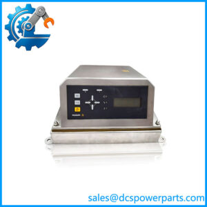
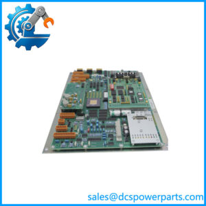
The N3000-IMC contains a master processor board, connector board supporting up to six additional plug-in I/O cards, and an internal slave processor with four potential-free relay outputs and four digital inputs. Up to two of those digital inputs can be used as frequency inputs.
The standard X20, X30, and X40 interfaces provide eight connections each for analog/binary sensors and actuators. The unit accepts 18–32 VDC, with 24 VDC as the nominal operating voltage, and provides two CANbus interfaces for integration into the wider alarm, monitoring, and control system.
Product Introduction
The NORIS Marine N3000-IMC is the master version of the N3000 I/O box, intended primarily for measurement acquisition and monitoring in marine engine-room installations. It collects signals from analog and binary sensors, monitors alarm limits and sensor faults, controls selected actuators, and communicates with other N3000 equipment through redundant CANbus and the internal iBus architecture.
The important distinction is that the -IMC is a complete I/O processing box rather than a single plug-in I/O module. Its six expansion positions can accommodate universal analog-input, analog-output, or digital I/O modules, allowing the hardware configuration to be adapted to the particular engine monitoring application.
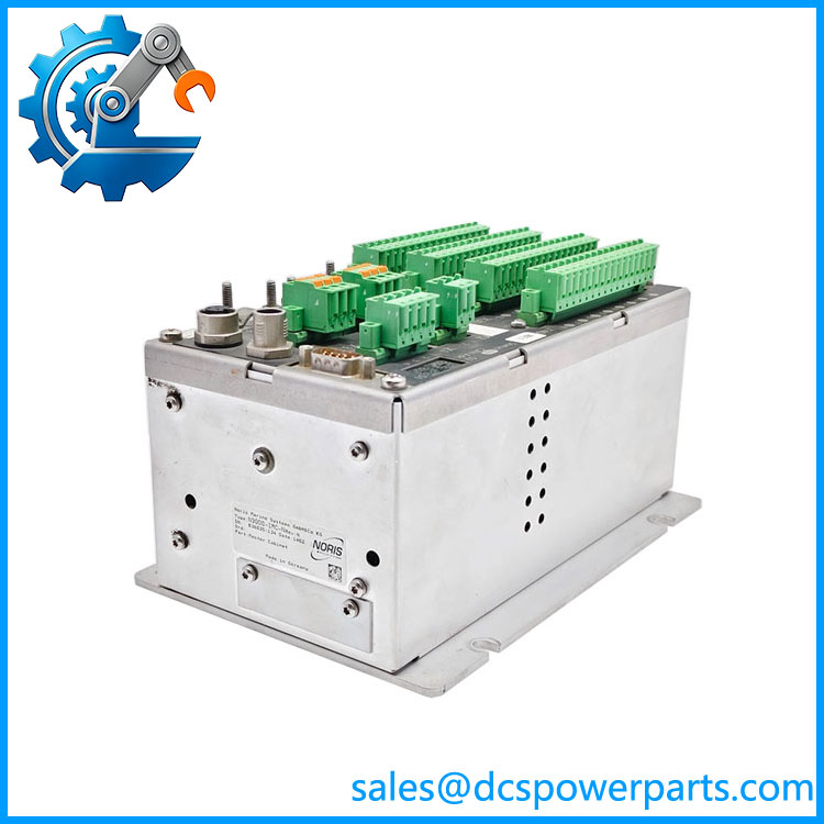
N3000-IMC
Application Scenarios & Field Pitfalls — Engineer’s Perspective
Engineering Pain Point
The main replacement risk is confusing the N3000-IMC master unit with the -ISC slave unit or with one of the plug-in I/O cards. The IMC has its own master processor and can control additional slave boxes and a display, while the ISC is subordinate to a master.
Typical Applications
- Marine engine monitoring — acquisition of temperature, pressure, level, speed, and status signals.
- Engine-room alarm systems — analog limit monitoring, binary status monitoring, and two-level alarm functions.
- Marine start/stop systems — control logic and hardwired start/interlock interfaces.
- Propulsion monitoring — equipment is documented in marine propulsion architectures alongside -ISC, -DSP, CANbus, and iBus equipment.
Technical Pitfalls to Avoid
- Do not confuse IMC with ISC.
is the master unit with the master processor and CAN-node control function. is an I/O slave unit connected to a master through iBus. - Check the installed plug-in cards.
ase can accept up to six additional I/O modules. The exact sensor and actuator capability therefore depends partly on which cards are installed in the six positions. - Verify the CAN configuration and address.
The unit has two CANbus interfaces, and the CAN address is set using the rotary address switch. Replacing the hardware without recording the existing network configuration can create communication or node-address problems. - Do not overlook redundant power.
The documented operating range is 18–32 VDC, nominal 24 VDC. The architecture can use alternate power sources through its designated connections, which is important in shipboard installations where monitoring must remain available during power-system disturbances. - Check the application configuration, not only the box.
Channel type, alarm thresholds, sensor-fault monitoring, actuator logic, CAN address, and installed plug-in cards form part of the working configuration. A repent should therefore be checked against the original system documentation before commissioning.
Related Products
- — I/O slave box that expands an master with additional sensor and actuator channels.
- — display unit used with marine monitoring systems.
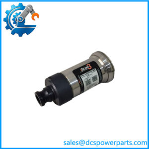
- universal analog input module — four-channel configurable analog input plug-in card.
- universal analog output module — four-channel configurable analog output plug-in card.
- digital I/O module — four configurable binary input/output channels.
- — protection unit used alongside equipment in documented marine engine architectures.
- — related larger-format I/O configuration; verify exact hardware designation before substitution.
Procurement Note
For an replacement, specify the complete designation and verify:
- installed plug-in I/O card types and positions;
- CANbus 1/CANbus 2 wiring;
- CAN node address;
- iBus connections to -ISC units;
- -DSP connection, if installed;
- 24 VDC power arrangement;
- alarm and limit configuration;
- sensor-fault/wire-break configuration;
- CompactFlash/data-logging option, if fitted.
The strongest documentation identifies as the master I/O box for marine data acquisition and monitoring, with expansion capability up to six plug-in I/O cards and control of up to three I/O slave boxes plus one slave display.