Description
Product Introduction (Non-Templated)
When a heavy-duty gas turbine trips unexpectedly during peak load demands, plant engineers immediately inspect the intermediate termination and relay logic cabinets. Locating a failing circuit board amidst a dense maze of wiring demands reliable component-level replacements that drop right into existing mounting footprints.
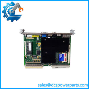
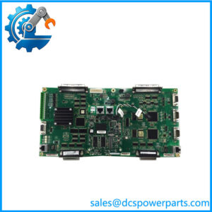
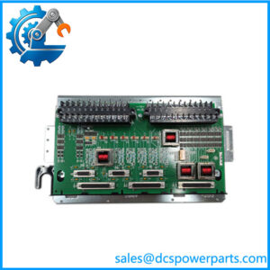
The 029.38089610 (ML101800034) serves as a specialized relay control board engineered for demanding turbine management environments. Utilizing this replacement assembly bypasses lengthy redesign cycles during critical legacy PLC replacement or emergency repair turnarounds.
Key Technical Specifications
- Board Type: Relay Control / Interface Printed Circuit Board
- Operating Temperature Range: -20°C to +70°C (-4°F to 158°F)
- Mounting Type: Chassis / Enclosure Rack Mount
- Construction: Industrial-grade multi-layer PCB with protective trace routing
- Termination: Heavy-duty barrier strip and plug-in headers
- Diagnostics: Board-level status LED indicators for active relay states
- Compliance: Designed for heavy industrial EMC and vibration resilience
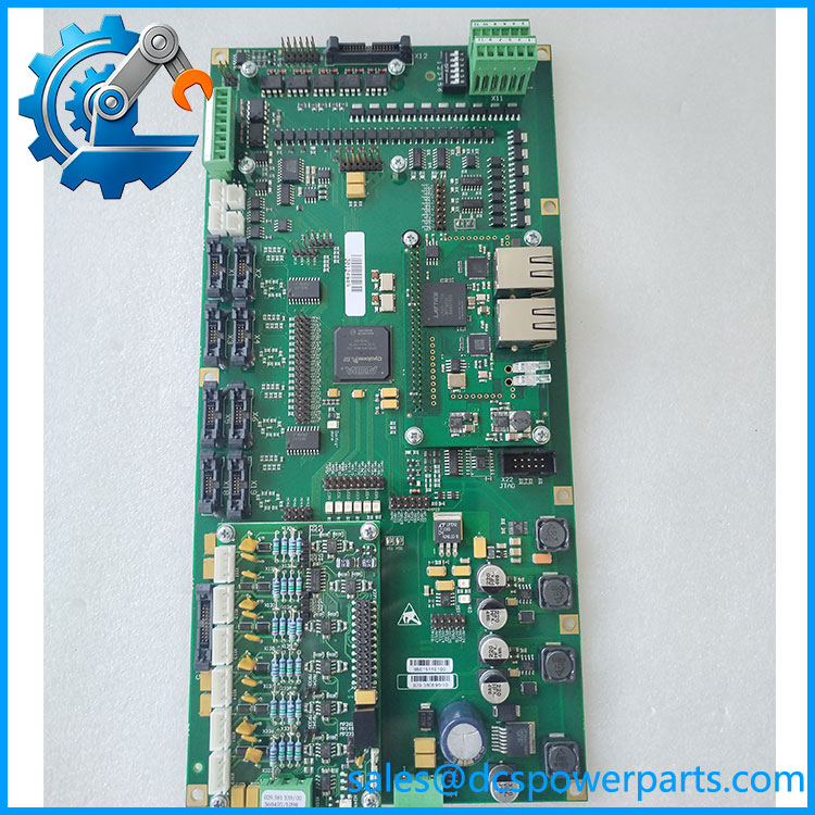
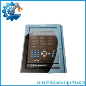
029.38089610 ML101800034
Application Scenarios & Pain Points
Unplanned outages on power generation skids lead to immense financial losses, making rapid component recovery essential for operations teams.
- Gas Turbine Skids: Handling critical solenoid valve actuation signals where contact degradation causes false trip signals.
- Compressor Stations: Managing auxiliary auxiliary motor starter interlocks exposed to heavy mechanical vibration.
- Heavy Manufacturing: Interfacing high-voltage field loads safely with low-voltage logic processors across continuous assembly plants.
A mid-stream gas compression facility in Oklahoma faced recurrent startup delays due to an intermittent relay latching failure on an older GE control flat. Swapping out the erratic assembly for a verified surplus 029.38089610 brought the compressor back online before the shifting window closed.
Related Products
- IS220PPDAH1A: PROFIBUS communication pack; handles digital network data exchanges instead of discrete hardwired relay switching, often found in adjacent rack slots.
- IS200EPVCH1A: Excitation control regulator board; manages generator field current regulation rather than general auxiliary relay logic functions.
- DS200TCQAG1B: Mark V thermocouple terminal board; terminates raw temperature sensor inputs upstream of the system’s main processor control hierarchy.
- IS220PTCCH1A: High-density thermocouple I/O pack; updates legacy temperature data acquisition loops within modernized Mark VIe architectures.
- IS220PAOCH1A: Analog output module; controls proportional valve positioning loops distinct from the binary switching behavior of relay boards.
The Engineer’s Guide: Field Pitfalls to Avoid
- Unchecked Coil Voltage Spikes: Failing to install or verify flyback diodes on inductive DC loads wired through the board can pit and weld the relay contacts shut over time. How to avoid: Inspect all external suppression elements on connected solenoids before energizing new relay outputs.
- Inadequate Conformal Coating Protection: Exposing raw solder joints to corrosive hydrogen sulfide or high-humidity atmospheres accelerates trace oxidation. How to avoid: Verify that replacement boards retain factory-applied conformal sealing, especially when deploying units into harsh coastal or outdoor shelters.
- Torque Mismanagement on Terminal Blocks: Overtightening screw terminals during wire reconnection can crack the board-mounted header bases (take it slow on those terminal blocks—snapping a header housing turns a 10-minute swap into a multi-hour soldering ordeal).
Frequently Asked Questions (FAQ)
- What do the two different part numbers (029.38089610 and ML101800034) signify? One identifier typically represents the primary manufacturing drawing or hardware part number while the secondary code designates internal tracking and revision tracing used by OEMs.
- Is this relay board field-repairable at the component level? While individual relays can technically be desoldered, strict regulatory standards on safety-critical turbine skids mandate complete board-level swaps rather than field-level micro-soldering.
- Can this board be installed in a live, powered-up rack? No, always remove system power prior to handling or replacing interface circuit boards to prevent voltage spikes across sensitive logic paths.
- What causes premature relay contact failure on this module? High inductive kickback from unsuppressed valves or drawing current loads beyond the specified relay amperage rating will rapidly degrade contact surfaces.
- Are surplus boards tested prior to shipping? Verified surplus units undergo rigorous bench simulation testing to verify proper coil pull-in voltage and contact continuity across every switching channel.