Description
Product Overview
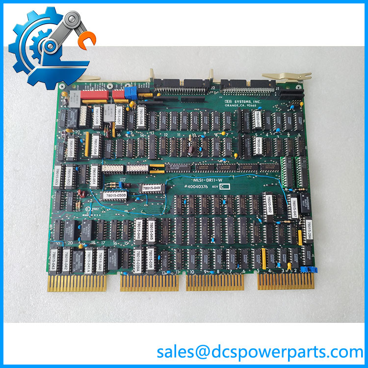
The MDB Systems MLSI-DR11-W is a legacy direct memory access (DMA) parallel interface board designed around the DR11-W interface concept. Its function is to provide a bidirectional data path between a host computer system and an external hardware device. Unlike a conventional PLC I/O card, which reads field inputs or controls industrial outputs, this board belongs to the computer-interface layer. It is relevant to legacy computing installations where external equipment must exchange data with a PDP-11 or VAX-class system through a parallel interface. Historical documentation identifies the MLSI-DR11-W Plus as an interface used in VAX/VMS software development and instrumentation applications.
The MLSI-DR11-W is particularly relevant when maintaining older test systems, laboratory equipment, data acquisition installations, and specialized computer-controlled instrumentation. A Fermilab technical newsletter documents an MDB MLSI-DR11-W-to-LeCroy 1821/DEC FASTBUS interface used with a VAX system for diagnostic work involving a 96-channel ADC. This provides a concrete example of its historical application, although it does not establish compatibility with every FASTBUS device or host configuration.
When sourcing the MDB Systems MLSI-DR11-W, the main engineering concern is compatibility with the original host bus, interface cabling, device-side protocol, and software driver. The board’s 16-bit data capability alone does not establish register mapping, DMA timing, interrupt behavior, or operating-system support. Buyers should also distinguish the standardro Plus. These names are related, but they should not be treated as interchangeable without comparing the board revisions, manuals, and software requirements. For a legacy installation, preserving the original configuration and obtaining a tested board with documented revision details are more important than relying on a generic description.
Product Introduction
Legacy computer-controlled instrumentation can become difficult to maintain when its original interface hardware fails. Replacing a DMA interface board requires more than matching its connector arrangement; bus timing, host configuration, device-side wiring, and driver behavior must also remain compatible.
The Sy provia -compatible parallel DMA interface for specialized legacy computing applications. Before replacement, confirm the board revision, host bus type, external cable assembly, and software environment.
Key Technical Specifications
| Parameter | Specification |
|---|---|
| Product model | |
| Manufacturer | MDB Systems |
| Alternate part number | 40040376 |
| Product type | DMA parallel interface board |
| Interface family | compatible |
| Data width | 16-bit, reported |
| Data transfer | Bidirectional parallel data exchange |
| DIP switches | 2, reported |
| Bottom-pin arrangement | 18 × 4, reported |
| Host platform | PDP-11/VAX-related applications; verify exact bus configuration |
| Communication protocol | Parallel DMA interface; not Ethernet or Modbus |
| Working voltage | Not confirmed |
| Operating temperature | Not confirmed |
| Installation method | Host-system board installation; exact slot and bus requirements need confirmation |
| Protection rating | Not established |
| Revision | REV. C reported in one listing; inspect actual board |
| Lifecycle status | Legacy; current production status unconfirmed |
The physical details above are based on available part-specific descriptions, not a verified manufacturer datasheet. Electrical limits, bus timing, DMA transfer rates, and interrupt specifications should not be assumed.
MLSI-DR11-W
Related Products and Interface References
| Model / Standard | Description | Engineering relevance |
|---|---|---|
| Plus | Related MDB Systems interface variant | Compare board revision, software support, and hardware configuration before substitution. |
| C | General-purpose DMA parallel interface | The interface concept against which the MDB board is identified. |
| DEC DRV11-WA | Related parallel interface hardware | Useful when reviewing legacy driver and host-interface documentation, but not automatically interchangeable. |
| LeCroy 1821 | FASTBUS segment manager | Documented in historical instrumentation applications using the MDB interface. |
| LeCroy 1885 | 96-channel ADC | Appears in the Fermilab diagnostic configuration associatit. |
Frequently Asked Questions
Q1: What is the primary function of the Sy?
It provia -compatible DMA parallel interface for bidirectional data exchange between a host computer and external equipment. It is legacy computer-interface hardware rather than a conventional PLC I/O module.
I compatible with PDP-11 and VAX systems?
It is associated with PDP-11/VAX-class interface applications. Actual compatibility depends on the host bus, system configuration, interface cabling, and operating-system driver. Verify the original installation documentation before assuming compatibility with a particular machine.
I a 16-bit interface?
Available product information identifies it as a 16-bit interface board. This does not establish its complete DMA timing, transfer rate, register map, or software behavior. Those details require the appropriate MDB documentation.
I Plus thee W?
They are related product designations, but should not automatically be considered identical. Check the board part number, revision, connector layout, and instruction manual before substituting one version for another.
Ca be hot-swapped?
Do not assume hot-swap support. This is legacy host-interface hardware, and removal may affect the host bus or connected equipment. Follow the original system shutdown and maintenance procedures before removing the board.
Qoe support firmware v3.1?
There is no verified firmware v3.1 compatibility information for this board. Its operation is more appropriately evaluated through the host operating system, device driver, interface software, and external equipment configuration.
Q7: What should be checked before purchasing a ac?
Confirm the complete part number, revision, board dimensions, pin arrangement, switch settings, and cable connections. Request photographs of both sides of the PCB and inspect the bottom pins for bending, oxidation, or damage. For used equipment, request functional test evidence under a compatible host and connected device configuration.
Procurement and Maintenance Considerations
belongs to a legacy computing environment, so replacement decisions should be based on the original system configuration rather than modern PLC specifications. A board that looks physically similar may still differ in bus behavior or software compatibility.
For procurement, request the actual board revision, clear PCB photographs, connector inspection results, and a description of the functional test performed. If the original system is still operational, record its switch settings and cable connections before removing the existing board.