Description
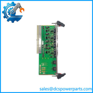
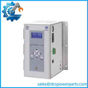
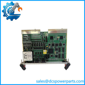
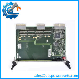
LenelS2 LNL-1320-S3B Dual Reader Interface Module
Product Overview
The LenelS2 LNL-1320-S3B is a Series 3 Dual Reader Interface (DRI) module designed for LenelS2 OnGuard access-control systems. Its job is to sit between the access-control network and two door reader interfaces, while also providing local input and relay-output resources for door monitoring, locking, alarm, and related access-control functions. The current LenelS2 documentation identifies the LNL-1320 as the Dual Reader Interface Module within the Series 3 architecture.
Unlike an industrial PLC I/O module, the LNL-1320-S3B is purpose-built for physical access control. Two reader ports can accommodate TTL reader signaling such as D1/D0 or Clock/Data, or 2-wire RS-485 reader communication including OSDP. Reader power can be selected for 12 VDC or pass-through operation, with up to 300 mA available per reader port according to the published specifications. Eight local inputs can be configured as supervised or unsupervised, while six Form-C relay outputs provide switching functions for door strikes, locks, alarms, and related equipment.
Power requirements are relatively modest: the Series 3 datasheet specifies 12–24 VDC ±10%, with maximum current depending on supply voltage and reader loading. At 12 VDC, the module is specified at up to 550 mA plus reader current; at 24 VDC, the maximum is 330 mA plus reader current. Communication with the intelligent system controller uses 2-wire RS-485, with a documented multi-drop distance of up to 4,000 ft.
For a legacy access-control installation, the LNL-1320-S3B should therefore be evaluated as a complete reader/door-interface component rather than as generic six-relay or eight-input hardware. Reader protocol, OnGuard controller architecture, power distribution, input supervision, relay contact loading, and Series 3 compatibility all matter during replacement.
Product Introduction
Two reader interfaces, eight configurable inputs, and six Form-C outputs put the LNL-1320-S3B at the door-interface level of an OnGuard installation. The module can support reader identification while simultaneously monitoring door and request-to-exit devices and controlling local relay loads.
For a legacy replacement, the Series 3 designation is important. Do not match only the LNL-1320 number; confirm the exact suffix, reader communication method, controller interface, and existing OnGuard configuration before swapping hardware.
Key Technical Specifications
| Parameter | Value |
|---|---|
| Product Model | LNL-1320-S3B |
| Manufacturer / Brand | LenelS2 |
| Product Series | Series 3 |
| Product Type | Dual Reader Interface Module |
| Access-Control Platform | OnGuard |
| Reader Ports | 2 |
| Reader Interface Types | TTL or 2-wire RS-485 / OSDP |
| Reader Power | 12 VDC selectable or pass-through |
| Reader Current | 300 mA maximum per reader port |
| Local Inputs | 8 |
| Input Configuration | Supervised or unsupervised |
| Relay Outputs | 6 |
| Output Type | Form-C contacts |
| NO Contact Rating | 5 A @ 30 VDC |
| NC Contact Rating | 3 A @ 30 VDC |
| Primary Power | 12–24 VDC ±10% |
| Maximum Current at 12 VDC | 550 mA plus reader current |
| Maximum Current at 24 VDC | 330 mA plus reader current |
| Controller Communication | 2-wire RS-485 multi-drop |
| RS-485 Maximum Distance | Up to 4,000 ft / 1,219 m |
| Mounting / System Role | Distributed reader/door interface |
| Platform Integration | LenelS2 OnGuard |
Specifications are based primarily on the current LenelS2 Series 3 datasheet.
Major Features / Practical Advantages
Dual reader interface
The principal function of the is handling two reader interfaces from one distributed access-control module. The reader ports support traditional TTL signaling, including D1/D0 and Clock/Data, as well as 2-wire RS-485 reader communication. OSDP compatibility is also documented for the RS-485 interface.
That flexibility is useful when upgrading reader hardware without redesigning the entire door-controller architecture. The actual reader protocol still needs to be confirmed during commissioning; having an RS-485 port does not automatically mean every connected reader is configured for the same protocol.
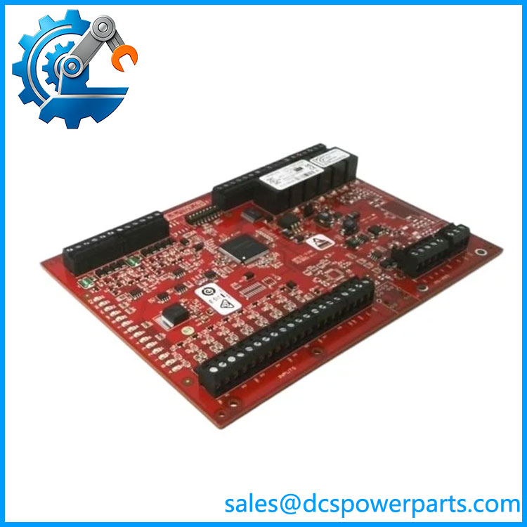
LNL-1320-S3B
Eight configurable inputs
Eight local inputs can be configured as supervised or unsupervised. This allows the module to monitor door position switches, request-to-exit devices, alarm contacts, and other discrete field signals associated with the controlled access point.
Input supervision is particularly important where the system needs to distinguish a normal contact state from a wiring fault. The resistance values and supervision configuration should be matched to the installed OnGuard configuration rather than improvised during replacement.
Six Form-C relay outputs
Six relay outputs provide local switching capability using Form-C contacts. The current specification lists 5 A at 30 VDC for normally open contacts and 3 A at 30 VDC for normally closed contacts.
These outputs can be used for access-control functions such as lock or strike control and alarm signaling. Even with the published contact ratings, engineers should check inrush current, inductive loads, suppression, and the actual lock or relay interface before connecting a field load directly.
12–24 VDC supply architecture
The module accepts 12–24 VDC ±10%. Current consumption varies with supply voltage and reader loading. The datasheet specifies a maximum of 550 mA at 12 VDC plus reader current, or 330 mA at 24 VDC plus reader current.
That distinction matters when several access-control modules share a common power supply. The reader current must be added to the module’s own consumption when calculating power-supply capacity.
RS-485 controller communication
The LNL-1320 communicates with the intelligent system controller over a 2-wire RS-485 multi-drop connection. The documented maximum communication distance is 4,000 ft (1,219 m).
In an existing installation, cable topology, termination, grounding, shielding, and addressing remain practical commissioning concerns. The nominal distance specification does not guarantee reliable communication under poor wiring conditions.
OSDP reader support
The Series 3 documentation specifically identifies 2-wire RS-485 / OSDP reader support. This is relevant when replacing older reader technology with newer secure-reader architectures while retaining the existing LenelS2 access-control infrastructure.
The reader itself, firmware, controller configuration, and OnGuard software version should all be checked before assuming that an OSDP migration is plug-and-play.
Distributed door-control architecture
The is part of a distributed access-control architecture. LenelS2 documentation shLNL-1320 alongside the LNL-1300 single-reader interface, LNL-1100 input-control module, and LNL-1200 output-control module on the RS-485 field network.
This makes the module particularly useful when the installation needs door-level processing rather than routing every reader and contact directly back to a central panel.
Related Products
- LNL-1300 — Series 3 Single Reader Interface Module for applications requiring one reader rather than two.
- LNL-1100 — Input Control Module used for distributed input expansion; the Series 3 architecture supports up to 16 inputs per LNL-1100.
- LNL-1200 — Output Control Module used for distributed output expansion, with up to 16 outputs per module in the documented architecture.
- Intelligent System Controller (ISC) — Supervisory controller architecture that communicates with distributed LNL interface modules over the access-control network.
- — The Series 3 Dual Reader Interface family designation; the complete suffix should be matched when procuring replacement hardware.
- LNL-1300 Series 3 — Appropriate where a single reader interface is required instead of the ‘s two-reader arrangement.
FAQ
Can I an with any ?
No. Confirm the complete part number and Series 3 hardware configuration. Reader protocol, controller architecture, input supervision, and software configuration should all be checked before installation.
Can I use both reader ports simultaneously?
Yes. The is specifically documented as a Dual Reader Interface module with two reader ports. The supported reader interface methods include TTL signaling and 2-wire RS-485 / OSDP.
Can I hthe ?
Do not assume unrestricted live replacement. The module is part of a distributed access-control system, so replacement should follow the site’s approved maintenance procedure and the LenelS2/OnGuard installation requirements. A live module swap can affect reader access, relay-controlled locks, alarms, or supervised inputs.
the support OSDP?
Yes. The current Series 3 documentation identifies 2-wire RS-485 / OSDP reader support. Confirm the connected reader’s protocol configuration and the corresponding OnGuard setup before migration.
What is the maximum RS-485 communication distance?
The published specification gives up to 4,000 ft (1,219 m) for the 2-wire RS-485 multi-drop connection. Actual field performance also depends on cable quality, topology, termination, grounding, and electromagnetic conditions.
the have relay outputs?
Yes. It provides six Form-C relay outputs. The published ratings are 5 A at 30 VDC for normally open contacts and 3 A at 30 VDC for normally closed contacts.
Does it support supervised inputs?
Yes. The Series 3 documentation specifies eight inputs, configurable as supervised or unsupervised. The actual supervision scheme should match the existing door-controller configuration.
What power suppthe require?
The primary supply is 12–24 VDC ±10%. At 12 VDC, the maximum specified consumption is 550 mA plus reader current; at 24 VDC, it is 330 mA plus reader current. Reader loading therefore has to be included in the power-budget calculation.
the work with OnGuard?
Yes. The Series 3 is part of the LenelS2 OnGuard access-control architecture. The current documentation shows it connected through an Intelligent System Controller and the RS-485 field network.
Does it support firmware v3.1?
The part number alone does not establish a specific firmware version. For a retrofit, verify the installed controller, reader technology, OnGuard software version, and approved Series 3 firmware combination rather than assuming firmware compatibility from the board number.
Procurement Note
For an replacement, verify the complete Series 3 part number and compare the existing field configuration before ordering. The important checks are the two reader types, TTL versus RS-485/OSDP configuration, reader power requirements, eight input supervision settings, six relay loads, RS-485 controller network, and available 12/24 VDC power capacity.
Do not select the replacement solely because the board has the same number of inputs and relays. This is an access-control interface with software-defined reader and supervision functions, not a generic relay expansion card. A technically correct replacement should reproduce the existing reader and door-control architecture without requiring undocumented changes to OnGuard configuration.
For new-surplus or refurbished inventory, request photographs of the actual label and PCB, confirm the exact marking, and distinguish unused surplus from previously installed equipment. Before commissioning, verify reader communication, supervised input states, relay operation, controller communication, and event reporting in the actual OnGuard system.