Description
Product Overview
1MRK002122-ABr05 is a revision-05 build of the short-range optical line data communication module fitted inside ABB Relion 670 terminals — the board catalogued as “Optical short range LDCM” and marked 670LDCM02 SHORT at the factory. It occupies a remote-communication position in a RED670, REG670, REL670, RET670 or REC670 chassis, and its single task is to move the sampled currents of a differential function between two line ends over one duplex multimode fiber pair, with the framing and timing needed to compare them.
A differential relay pair is only as trustworthy as the channel joining it, and the payload explains why. Every 5 ms the module sends three-phase current samples, the time reference aligning both terminals, trip and block indications, alarms and eight binary signals available for transfer trip or interlocking. Framing slips and clock misalignment therefore reach the protection function directly, which is the reason this board is specified and documented as protection equipment rather than as a general communication card.
The limits that govern its use are optical, not logical. On 62.5/125 µm graded-index glass the module carries 13 dB of budget and roughly 3 km of reach; on 50/125 µm it delivers 9 dB and about 2 km, with −17 dBm minimum launch against −30 dBm receiver sensitivity. Together with the documented loss assumptions of 3 dB/km, 1.5 dB per ST connector, 0.5 dB per repair splice and a 0.1 dB/km aging margin, those figures support a feasibility decision from a route survey before a single module is ordered.
Technical Specifications
表格
| Parameter | Value |
|---|---|
| Model | 1MRK002122-ABr05 |
| Hardware revision | r05, same electrical specification as r03 and r09 |
| Manufacturer | ABB, Sweden |
| Product type | Optical short range line data communication module, IED plug-in board |
| Optical port | ST duplex, transmit and receive pair |
| Fiber specification | Graded-index multimode 62.5/125 µm standard; 50/125 µm accepted |
| Wavelength | 820 nm peak, 865 nm nominal, 792 nm minimum |
| Optical budget | 13 dB on 62.5/125 µm, 9 dB on 50/125 µm |
| Reach | Roughly 3 km and 2 km respectively, by link calculation |
| Launch power and sensitivity | −17 dBm minimum output on 62.5/125 µm, −30 dBm receiver sensitivity |
| Protocol and framing | IEEE C37.94 synchronous, HDLC |
| Data rate | 64 kbit/s default, 2 Mbit/s mode selectable |
| Telegram payload | Three-phase currents every 5 ms, time reference, trip/block/alarm, eight binary signals |
| Channels per terminal | Up to four remote communication interfaces |
| Power | Supplied from the IED backplane, no separate connection |
| Slot positions | P30:5, P30:6, P31:3, P32:2, P32:3 by chassis variant |
| Compliance | IEC 60255-26 EMC, IEC 60255-1 and IEC 60255-27 for the parent IED |
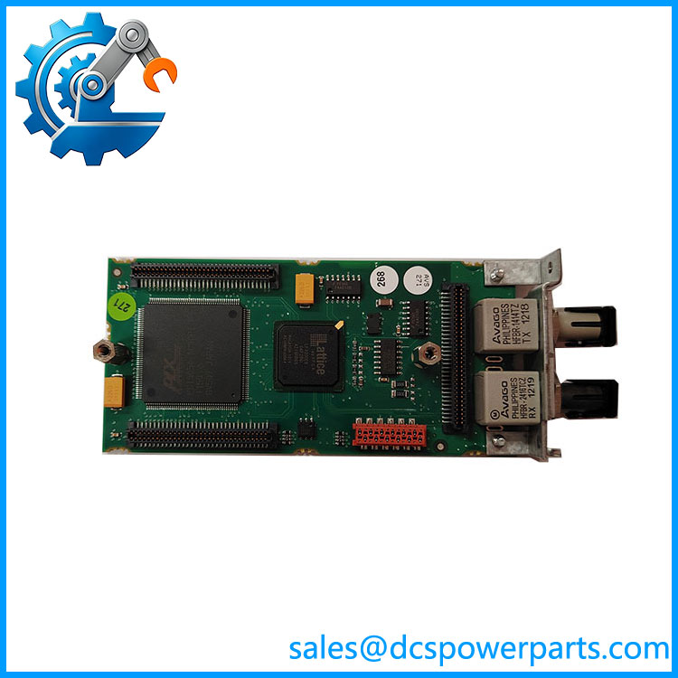
1MRK002122-ABr05
Key Features and Advantages
What the 5 ms telegram commits the link to
Because the frame leaves every 5 ms and carries the timing reference along with the samples, the link must deliver continuity rather than raw bandwidth. A 64 kbit/s channel is ample for the payload; what matters is that frame alignment and clock relationship survive disturbances. 1MRK002122-ABr05 supervises exactly those, so a degrading fiber announces itself as a channel alarm long before it becomes an unexplained operation during a fault.
Multimode reach read as a cost decision
Where both ends share a compound, an industrial site or adjacent substations, the 13 dB budget covers the route and single-mode components never enter the project — no FC/PC transceivers, no fusion splicer, no lease. Evaluating reach against the budget assumptions rather than against a nominal “3 km” figure is what keeps a marginal link from being commissioned with a margin that disappears after five summers of connector ageing.
Optical power chosen to protect the receiver
The low and high output settings exist for a reason beyond reach. On a 200 m intra-station patch, running full power can drive the receiver toward saturation and hide real losses; on a 2.5 km run, the extra 3 dB of high-power mode is what preserves margin. Setting the level from measured loss, as the application guide recommends, keeps both extremes out of trouble.
Revision level kept inside the asset record
1MRK002122-ABr05 is functionally interchangeable with r03 and r09 in the same position, but the revision label is part of traceability. Recording it in the maintenance file keeps a subsidence or repeat-failure investigation readable years later, when nobody remembers which build was installed where.
Applications
Retrofit programmes on ageing substations account for a large share of deployments: where a 670 terminal replaced an earlier protection panel, and the two line ends sit within a few kilometers of each other in fiber terms, this board closes the differential loop using the multimode glass already present in the cable trench. No new single-mode route, no change to the telecom contract, and no additional terminal equipment in the opposite station.
Cascade hydro stations along one river use 1MRK002122-ABr05 to link successive REG670 terminals, each pair a kilometer or two apart. Urban cable networks apply it between neighboring distribution substations, where the route is short but an uncleared fault is measured in customer minutes. Industrial captive grids — mine feeder lines, steel works interties, refinery internal transmission, airport and data-centre HV distribution — use the same board to obtain unit protection across a private network of a few kilometers.
Schemes that need only binary signal transfer specify it as well: interlocking between busbar and line protection, transfer trip from external relays, or status exchange for a sequential black-start, all sharing the supervised pair with the current telegram. Commissioning teams also use spare modules back to back over a short patch cord to prove the differential function before energization.
Related Products
1MRK002311-AA — medium range LDCM, single-mode 9/125 µm at 1310 nm with FC/PC connector and 22 dB budget for routes of 60 to 80 km. 1MRK002311-BA — long range LDCM at 1550 nm, 26 dB budget, covering 110 to 130 km. 1MRK005500-AA — Ethernet SFP, optical LC connector, for IEC 61850 station bus traffic. 1MRK005500-BA — Ethernet SFP, RJ45 connector, the copper station-bus alternative. 1MRK002266-EA — optical Ethernet module for station communication on the same platform. 1MRK001608-AB / 1MRK001608-BB / 1MRK001608-CB — serial modules for SPA, LON, DNP and IEC 60870-5-103 in plastic, plastic-glass and glass versions. 1MRK002309-AA — galvanic RS485 module for short copper links inside a station. 1MRK007002-AA — GPS time module, used where the differential function takes its clock from a global reference. 1MRK002282-AB — IRIG-B synchronization module, the other external time base. RED670 / REG670 / RET670 — terminals hosting 1MRK002122-ABr05 in line, generator and transformer protection.
Installation and Maintenance
Before installation: note the revision on the label and enter it in the asset record, then confirm the chassis has a free remote-communication position at P30:5, P30:6, P31:3, P32:2 or P32:3 according to its case variant. Establish how many channels the scheme needs — one for a two-ended line, two per end for a three-ended line, a main and standby pair for redundancy. Sweep the route with an optical time-domain reflectometer, compare the result with the 13 dB budget, and set the optical power level from the remaining margin: low for runs up to about 1 km, high beyond. Isolate the IED before fitting 1MRK002122-ABr05.
Maintenance practice: clean ST ferrules before every mating and after any intervention at the fiber panel, since a contaminated end face consumes budget faster than two decades of aging. Record launch and received levels at commissioning and repeat the measurement annually; a 2 to 3 dB drop indicates connector wear rather than a failing module. Restore the channel configuration from the stored parameter set, verify that one end remains clock master and the other slave, run a loop-back test, and read the supervision counters before returning the protection to service. Keep spare 1MRK002122-ABr05 units capped, labeled by revision, and stored within the parent IED’s environmental range.
Warranty and Quality
1MRK002122-ABr05 is supplied as a plug-in module whose revision level is printed on the label and repeated in the packing documentation, so the receiving station knows precisely which build enters which position. Every unit passes a fiber loop-back verification covering launch power, received level, frame lock and channel status, and the measurement record travels with the shipment. A 12-month warranty applies under standard substation-automation practice with repair or replacement for quality-related failure. Where a scheme relies on several modules at once, sets are checked for revision consistency before dispatch, and support covers slot mapping, clock role configuration, budget review from survey data and the low or high power decision.
免费
今天 10:08