Description
Kyma KDU-210 Display Unit
Product Introduction
Marine operators need the shaft-power measurement system to present usable information where the machinery is actually being monitored, not only on a remote engineering computer. The Kyma KDU-210 is a dedicated display unit for Kyma’s Shaft Power Meter and Ship Performance systems, providing the operator interface for measured and calculated propulsion-performance information. Kyma documentation identifies KDU as the display unit and shows KDU-210 installations in engine control rooms, wheelhouse consoles, and other operator locations.
The KDU-210 uses a separate terminal strip or terminal data logger architecture rather than functioning as a standalone PLC. Its documented interfaces include RS-485, RS-422, and RS-232 ports, while system-specific configurations can use serial connections to a computer or Kyma equipment. The unit operates from a 12 VDC supply at the display, with the associated terminal equipment supplied from 85–264 VAC. For replacement work, the exact KDU configuration and supplied cable set matter—Kyma upgrade documentation specifically warns that KDU-200 wiring should not simply be reused with a KDU-210/220 installation.
Key Technical Specifications
| Parameter | Specification |
|---|---|
| Product Model | KDU-210 |
| Manufacturer | Kyma |
| Product Type | Display Unit |
| Application | Kyma Shaft Power Meter / Marine Performance Monitoring |
| Display Supply | 12 VDC |
| Display Current | 0.8 A |
| Display Power | 10 W |
| Terminal Strip Supply | 85–264 VAC |
| AC Frequency | 47–63 Hz |
| Terminal Strip Power | 25 W |
| Ambient Temperature | 0 to 50°C |
| Display Dimensions | 211.5 × 160 × 86.3 mm |
| Terminal Strip Dimensions | 200 × 100 × 75 mm |
| Display Weight | Approx. 2.2 kg |
| Terminal Strip Weight | Approx. 0.9 kg |
| Display Ingress Rating | IP20 |
| Terminal Strip Ingress Rating | IP65 |
| Serial Interfaces | RS-232, RS-422, RS-485 |
| Installation | Flush console or bracket mounting |
| Typical System Location | Engine Control Room / Wheelhouse |
The electrical and dimensional values above come from Kyma Shaft Power Meter documentation. The actual serial-port assignment depends on the system configuration; one documented configuration reserves COM1 and COM2 while COM3 and COM4 are available for external equipment.
Major Features / Advantages
Dedicated Kyma Operator Interface
The is designed around Kyma’s marine performance-monitoring architecture. It is not simply a generic industrial touchscreen. In a Kyma Shaft Power Meter installation, the display provides the local human-machine interface for information generated by the shaft-power measurement system. In Ship Performance configurations, units can also be installed at multiple operator positions, such as the engine control room and wheelhouse.
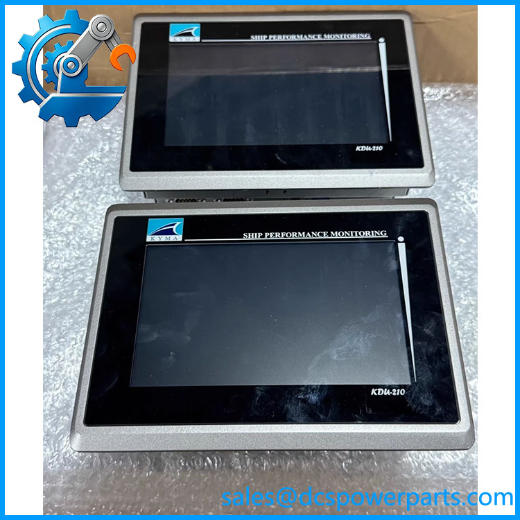
KDU-210
Multiple Serial Communication Interfaces
Serial communication is central to the architecture. Published documentation identifies RS-232, RS-422, and RS-485 interfaces, with individual ports assigned according to the system configuration. This allows the display to communicate with the associated terminal equipment, system computer, or other approved Kyma equipment without treating the display as an independent PLC controller.
Marine Console Installation
The display was designed for installation in shipboard control consoles. Kyma documentation identifies both flush and bracket mounting arrangements. The terminal strip is installed separately, normally on a 35 mm DIN rail, with dedicated cables connecting it to the display.
Separate Display and Terminal Power Architecture
One detail that can easily cause confusion during procurement is that the published power figures do not describe a single AC-powered display. The terminal strip receives 85–264 VAC, while the display itself is supplied with 12 VDC at up to 0.8 A. The documented system specification lists 25 W for the terminal-strip supply and 10 W for the display.
Useful for Legacy Marine System Maintenance
units remain relevant when maintaining existing Kyma Shaft Power Meter and Ship Performance installations. The important point is configuration matching. A may be physically similar to another display while carrying different software, port assignments, cable arrangements, or location indexing. Kyma documentation identifies units as .x, with the index corresponding to the intended installation location.
Application Scenarios & Pain Points
Engine Control Room Display
A can be installed in the engine control room to provide local access to shaft-power measurement and propulsion-performance information. Kyma project documentation specifically identifies .1 as an ECR display in a documented KSP installation.
Wheelhouse Monitoring
A second can be installed in the wheelhouse or another operator console. The system documentation identifies .2 for wheelhouse installation, with the associated terminal equipment and serial connection defined separately.
Shaft Power Measurement Systems
The display works with Kyma shaft-power measurement equipment, where torque, shaft power, and rotational-speed information are acquired and presented to operators. It therefore belongs to the broader KPM/KSP measurement architecture rather than a conventional PLC I/O system.
KDU-200 Replacement Projects
The is also encountered during upgrades from older KDU-200 displays. This is an area where field assumptions can cause trouble: Kyma’s upgrade procedure explicitly states that the old KDU-200 cables should not simply be reused because the wiring to the /220 is different, even where connectors may appear identical.
Related Products
- Kyma KDU-200 — Earlier-generation Kyma display unit that can be encountered in legacy KPM installations.
- Kyma KDU-220 — Later display model covered by Kyma’s /220 upgrade documentation.
- Kyma KDU-300 — Larger Kyma display unit used in related shaft-power measurement architectures.
- KDU-TS200 — Terminal strip used with KDU display installations.
- KDU-TD210 — Terminal data logger used in applicable Kyma Ship Performance configurations.
- KDU-C211 — Power cable connecting the KDU display to associated terminal equipment.
- KDU-C212 — Signal cable used for applicable serial connections.
- KDU-C214 — Signal cable used in documented wheelhouse configurations.
- SPS-210 — Kyma shaft-power measurement system component associated with the shaft sensor installation.
The exact accessory combination depends on whether the is installed as part of a KPM or KSP system and on its assigned location.
Engineer’s Guide — Field Pitfalls to Avoid
1. Do not treat as a generic PLC/HMI.
It is a Kyma Display Unit designed for the KPM/KSP architecture. A generic display with similar electrical characteristics is not an automatic substitute.
2. Verify the KDU index number.
Kyma documentation uses identifiers such as and to associate individual displays with specific locations. Mixing the physical unit with the wrong terminal equipment or configuration can create communication problems.
3. Do not reuse KDU-200 cables by assumption.
Kyma’s upgrade procedure explicitly warns that the wiring for /220 differs from . Even if connectors look identical, the cable should be replaced with the specified /220 cable set.
4. Verify serial-port assignment.
The documentation identifies different RS-232, RS-422, and RS-485 connections. Port numbers are configuration-dependent, so a simple pin-for-pin assumption from another installation is risky.
5. Check software and configuration before installation.
The is not only a passive screen. Kyma testing documentation calls for recording the module type, serial number, software version, and master/slave/WDU status during testing. Those details should be captured before replacing an installed unit.
6. Confirm the complete assembly, not only the display.
The display, terminal strip/data logger, cables, and mounting hardware form a system-specific installation. Procurement should identify which of these items are actually included with the offered unit.
FAQ
What is the Kyma ?
The is a Kyma Display Unit used in Kyma Shaft Power Meter and Ship Performance systems. It provides the operator interface for marine shaft-power and performance-monitoring applications.
Is a PLC?
No. It should be classified as a display/operator interface within the Kyma marine performance-monitoring system, rather than as a general-purpose PLC or DCS controller.
What power supply does use?
The published system specification lists 12 VDC, 0.8 A, 10 W for the display. The associated terminal strip is supplied from 85–264 VAC, 47–63 Hz, with a published 25 W figure.
What communication interfaces are available?
Published documentation identifies RS-232, RS-422, and RS-485 interfaces. The exact port assignment depends on the installation configuration.
Can replace a directly?
Not as a simple cable-and-display swap. Kyma’s documented -to-/220 upgrade procedure specifically warns that the old cables should not be reused because the wiring is different. The supplied /220 cables and the corresponding terminal connections should be used.
What should I verify before purchasing a ?
Verify the exact model, software/configuration version, serial-port assignment, KDU index/location, included terminal equipment, cable set, mounting arrangement, and actual hardware condition. For a vessel already in service, compare the replacement unit against the original system drawings rather than relying only on the model number.
Is suitable for marine applications?
Yes. It was specifically documented for Kyma marine shaft-power and ship-performance systems, including engine-control-room and wheelhouse installations. The published documentation specifies an operating ambient range of 0 to 50°C.