Description
GE IS200BICLH1A IGBT Drive/Source Bridge Interface Board
Product Introduction
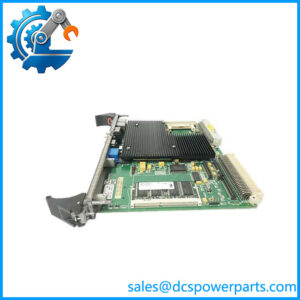
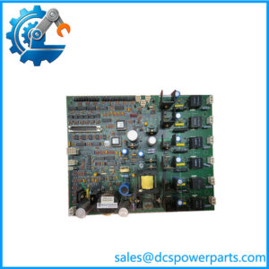
The General Electric IS200BICLH1A is an IGBT Drive/Source Bridge Interface Board, identified by the functional abbreviation BICL, for GE Innovation Series drive-control equipment. Its primary role is to provide the interface between the Innovation Series Drive main control board and the Bridge Personality Interface Boards used by the drive power section. Documented compatible bridge-interface hardware includes BPIA, BPIB, and SCNV boards. The GE IS200BICLH1A therefore belongs to the drive-control and power-conversion interface layer rather than serving as a conventional PLC field I/O module.
The GE IS200BICLH1A also handles several supporting monitoring and control functions. Available technical records identify four RTD inputs for temperature-related monitoring, two fault-string inputs, and one PWM output associated with fan-speed control. The board provides bridge and ambient temperature monitoring and interfaces with the system fault display. A 1024-bit serial memory device stores board identification and revision information. Four relays are also installed on the PCB. The board connects to the rack through P1 and P2 backplane connectors and has a faceplate marking specifying installation in Slot 5.
For procurement, the exact GE IS200BICLH1A identifier deserves attention because related BICL versions are not automatically interchangeable. In particular, later configurations such as IS200BICLH1ACB carry different functional/artwork revision information; available documentation indicates that the base A revision has different compatibility considerations from the CB revisions. The replacement should therefore be matched against the installed board’s complete identifier, revision markings, associated bridge boards, rack position, and system documentation. GE manual GEI-100264 is the relevant technical reference identified for this board.
Technical Specifications
| Parameter | Specification |
|---|---|
| Product Model | IS200BICLH1A |
| Manufacturer | General Electric |
| Product Family | Innovation Series / IS200 |
| Functional Abbreviation | BICL |
| Product Type | IGBT Drive/Source Bridge Interface Board |
| Primary Application | Innovation Series drive control |
| Main Function | Drive-to-bridge interface |
| Associated Boards | BPIA, BPIB, SCNV |
| Rack Type | VME-type |
| Backplane Connectors | P1, P2 |
| Installation Position | Slot 5 only |
| RTD Inputs | 4 |
| RTD Resolution | 10-bit, according to secondary technical records |
| Fault-String Inputs | 2 |
| PWM Outputs | 1 |
| Temperature Monitoring | Bridge and ambient |
| Relays | 4 |
| Serial Memory | 1024-bit |
| Clock | 20 MHz reported by secondary technical records |
| Front LEDs | None reported |
| Front User Ports | None reported |
| Fuses | None reported |
| Adjustable Hardware | None reported |
| Functional Revision | A |
| Primary Documentation | GEI-100264 |
| Power Requirement | +5 VDC / 6 A reported by secondary sources; verify against the actual rack/system power documentation |
| Operating Temperature | -40°C to +70°C reported by secondary sources; verify against cabinet/system documentation |
| Protection Rating | No standalone board-level IP rating established |
The +5 VDC/6 A and -40°C to +70°C figures appear in secondary technical listings rather than a primary GE datasheet available for direct verification. They should therefore be treated as procurement-reference data rather than cabinet-level design limits.
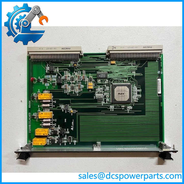
IS200BICLH1A
Main Features and Engineering Considerations
Dedicated bridge-interface function
The defining characteristic of the is its position between the Innovation Series Drive main control board and bridge personality hardware. BPIA, BPIB, and SCNV boards are identified as associated bridge interfaces. This architecture means the BICL should not be selected or tested as if it were a standard digital or analog PLC card.
VME rack installation
The board uses P1 and P2 backplane connectors and is designed for a VME-type rack. The faceplate is marked for Slot 5 only. This is an important field detail: inserting the board into an incorrect rack position can expose the board to an incorrect electrical connection. GE-related technical documentation specifically warns about correct slot installation.
Temperature monitoring
Four RTD inputs are associated with the board, providing temperature-monitoring capability for the drive/bridge environment. Bridge and ambient temperature information can be important when diagnosing drive cooling or power-stage faults. A temperature alarm should not automatically be interpreted as a BICL PCB failure; the RTD circuit, wiring, bridge hardware, and associated control logic should be checked as a system.
Fan-speed control
The BICL includes a PWM interface associated with fan-speed control. This provides a control path for drive cooling equipment. When troubleshooting a cooling fault, technicians should distinguish between a missing PWM command, a fan/power problem, and an actual BICL hardware failure.
Fault-string interface
Two fault-string inputs are reported for the board. These provide system-level fault information rather than conventional process-variable acquisition. Fault-string behavior should therefore be checked against the Innovation Series drive documentation and the associated control-board configuration.
Board identification memory
The 1024-bit serial memory device stores board identification and revision information. This matters during replacement because the installed hardware revision can affect configuration and compatibility. A replacement should be documented against the original board label rather than identified only by the broad BICL family name.
Base A revision versus later variants
The supplied model is , the base A functional revision. Related models such as IS200BICLH1ACB and IS200BICLH1B should not be assumed to be direct substitutes. Available technical records specifically distinguish the base A revision from later CB revisions in terms of backward compatibility.
Application Scenarios
- GE Innovation Series drive systems
- GE IS200 drive-control hardware
- IGBT drive bridge interfaces
- Source-bridge control architectures
- BPIA/BPIB bridge-interface systems
- SCNV-associated drive systems
- Bridge temperature monitoring
- Ambient temperature monitoring
- Drive cooling-fan control
- System fault-string monitoring
Engineer’s Guide: Field Pitfalls
Do not treat as generic PLC I/O.
Its primary job is communication and signal interfacing between the drive control board and bridge personality hardware.
Install it in the specified rack position.
The board faceplate is marked “Install in Slot 5 Only.” An incorrect VME slot can expose the board to an inappropriate backplane connection.
Verify P1 and P2 connections.
Both backplane connectors are part of the board’s system interface. Poor seating or contamination can create multiple simultaneous symptoms.
Check the bridge boards before condemning BICL.
BPIA, BPIB, and SCNV are part of the associated architecture. A bridge-side failure can present as a communication or drive-control problem at the BICL level.
Check RTD circuits independently.
The four RTD inputs are used for temperature-related monitoring. An abnormal temperature reading can originate from the sensor, wiring, connector, or bridge rather than the BICL PCB.
Check cooling hardware separately.
The PWM fan-control interface means that a cooling fault may involve the fan, power supply, wiring, or upstream control logic.
Do not assume all BICLH1 variants are interchangeable.
The base has different revision status from CB and other variants. Confirm the complete installed identifier before substitution.
Use ESD precautions.
The board contains programmable logic, memory, relays, and other semiconductor devices. Handle it using appropriate static-control procedures.
Frequently Asked Questions
What is ?
is a GE IGBT Drive/Source Bridge Interface Board, or BICL, used in the Innovation Series drive architecture. It interfaces the main drive control board with bridge personality interface hardware.
What does BICL stand for?
BICL identifies the IGBT Drive/Source Bridge Interface function of the board.
Which boards are associated with ?
The documented associated bridge personality boards include BPIA, BPIB, and SCNV.
How many RTD inputs does the board have?
Secondary technical records identify four RTD inputs, used for temperature monitoring.
How many fault-string inputs are provided?
Two fault-string inputs are reported for the .
Does the board have an Ethernet port?
No standalone Ethernet port is documented for the . Its primary system connection is through the P1/P2 VME backplane interface.
Does have a front-panel display?
No dedicated LEDs or operator display are reported. The faceplate is largely blank apart from identification and installation hardware.
Where should be installed?
The board carries a Slot 5 installation designation. This should be confirmed against the actual rack documentation before installation.
What is the difference between and IS200BICLH1ACB?
Both are BICL boards, but they represent different revision configurations. Available documentation indicates that CB revisions have different compatibility characteristics from the base A revision. They should not be substituted solely on the basis of the shared base designation.
What documentation should be checked?
GE document GEI-100264, identified as the IGBT Drive/Source Bridge Interface manual, is the principal technical reference associated with .
Procurement Note
For a legacy GE Innovation Series drive, should be procured as an exact BICL bridge-interface board rather than as a generic GE control PCB. Before purchasing, verify the complete board identifier, functional revision, rack position, P1/P2 connectors, associated BPIA/BPIB/SCNV hardware, RTD circuits, fan-control interface, and fault-string wiring.
For surplus or repaired hardware, request clear photographs of the board identification label and connector areas. A practical incoming inspection should include visual PCB inspection, connector condition, relay verification, RTD-channel checks, memory/board identification where supported, and controlled rack-level functional testing before returning the board to service.