Description
ICS Triplex TC-205-02-8M5 | Trusted I/O Companion Slot Cable | 40-Channel Output to FTA
Key Technical Specifications
| Parameter | Specification |
|---|---|
| Manufacturer | ICS Triplex |
| Current Platform | Rockwell Automation Trusted |
| Part Number | TC-205-02-8M5 |
| Product Type | I/O Companion Slot Cable |
| Cable Category | Internal Companion Slot |
| Signal Direction | 40-channel output to FTA |
| Cable Length | 8.5 m |
| Insulation Code | 02 — LSZH |
| Flame Retardancy | IEC 60332-3 Category A |
| Chassis End | 2 × 96-way Type-C connectors |
| FTA End | 1 × 96-way Type-R connector |
| Nominal Voltage Class | 30 VDC reference rating reported by secondary documentation |
| Isolation Rating | 500 VDC reference value reported by secondary documentation |
| Conductor Reference | 120 × 24 AWG / 0.22 mm² reported |
| Installation | Internal cabinet / adjacent Trusted chassis |
| Recommended Maximum I/O Cable Length | 15 m |
The Trusted cable documentation identifies the TC-205 family as an I/O Companion Slot cable for output modules, with connections between Trusted analog/digital output modules and FTAs or VFTAs. The cable length is specified in 0.5 m increments, making the 8M5 suffix an 8.5 m configuration. The 02 insulation code identifies LSZH cable material, which also meets IEC 60332-3 Category A flame-retardant requirements.
Product Introduction
The ICS Triplex TC-205-02-8M5 is an internal Trusted I/O Companion Slot cable used to connect a Trusted output module to a Field Termination Assembly (FTA). It is part of the Trusted TMR I/O wiring architecture and is designed around the specific connector and signal arrangement used by Trusted chassis and termination hardware. It is therefore a system-specific cable assembly rather than a generic multiconductor industrial cable.
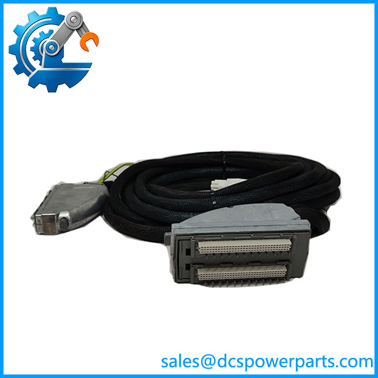
The TC-205-02-8M5 provides a 40-channel output connection and uses two 96-way Type-C connectors at the chassis end and a 96-way Type-R connector at the FTA end. The 8.5 m length is useful where the associated termination hardware is positioned some distance from the Trusted chassis, but cable length should still be considered against voltage drop, noise, crosstalk, and cabinet routing requirements.
TC-205-02-8M5
Application Scenarios & Field Pitfalls — The Engineer’s Perspective
Engineering Pain Point
In a Trusted system, replacing a cable with one that merely has the correct number of conductors is not an acceptable substitute. The connector families, signal allocation, cable type, length, and output-module relationship are part of the system design. A cable with an incorrect pinout can put the wrong field signal on the wrong termination point, so the complete TC part number should be matched before installation.
Typical Applications
Trusted output module connection
The TC-205 family connects Trusted output modules to the associated FTA, carrying the module’s field-output signals to the termination assembly.
Trusted TMR safety-control cabinets
The cable is used within Trusted I/O architectures where distributed termination and modular I/O are required.
Remote or separated termination arrangements
The 8.5 m length allows the FTA to be positioned away from the Trusted chassis while remaining within the recommended cable-length range.
Legacy Trusted system maintenance
This cable is particularly relevant when maintaining installed Trusted systems where original cable assemblies may be difficult to source.
Technical Pitfalls
- Do not confuse TC-205 with TC-201.
The TC-201 family is associated with a 40-channel input-to-FTA arrangement, whereas TC-205 is specified for a 40-channel output-to-FTA connection. - Do not confuse TC-205 with TC-203.
TC-203 is an external Companion Slot cable family, while TC-205 is identified as an internal cable. The physical installation environment is therefore different. - The 02 suffix matters.
The02portion specifies LSZH insulation. Other insulation variants use different part-number coding and should not be treated as identical assemblies. - The 8M5 suffix is the cable length.
8M5corresponds to 8.5 m. Trusted documentation specifies cable length in 0.5 m increments. - Observe the 15 m recommendation.
Trusted documentation recommends keeping I/O cable length at or below 15 m where practical. Longer runs can introduce voltage drop, offset, crosstalk, and noise concerns. - Protect the cable during routing.
Internal Companion Slot cables are intended for cabinet/enclosure installations. They should not be dragged by the connectors or routed through an unprotected external cable path. - Check the connector arrangement before ordering.
The chassis end uses two 96-way Type-C connectors in a double-width hood, while the FTA end uses a 96-way Type-R connector. Connector appearance and pin assignment should be checked against the installed Trusted hardware.
Related Products
- ICS Triplex TC-205-02-4M5 — Same internal 40-channel output-to-FTA family, 4.5 m length.
- ICS Triplex TC-205-02-6M5 — Same output cable family, 6.5 m length.
- ICS Triplex TC-205-02-10M5 — Same output cable family, 10.5 m length.
- ICS Triplex TC-205-02-12M5 — Same output cable family, 12.5 m length.
- ICS Triplex TC-201-02-8M5 — Internal 40-channel input-to-FTA cable; different signal direction.
- ICS Triplex TC-203-02-8M5 — External Companion Slot cable, 40-channel input-to-FTA arrangement.
- ICS Triplex TC-215-02-8M5 — Related Trusted output cable family; verify exact module and FTA compatibility.
- ICS Triplex TC-303-02-4M0 — Trusted Expander cable; different function from an I/O Companion Slot cable.
- ICS Triplex TC-302-02-4M0 — Trusted controller-end expander cable; not an I/O-to-FTA cable.
Procurement Note
For TC-205-02-8M5, the complete part number is important: TC-205 identifies the output Companion Slot configuration, 02 identifies LSZH insulation, and 8M5 specifies 8.5 m length. Match the cable against the exact Trusted output module, FTA/VFTA, cabinet arrangement, and connector configuration before substitution.
For used or surplus inventory, inspect both 96-way chassis connectors and the Type-R FTA connector for bent contacts, contamination, cracked housings, latch damage, and evidence of excessive pulling. Check the cable jacket along its full 8.5 m length for crushing or tight bend damage. In a safety-system application, do not rely on continuity alone; verify the pin-to-pin mapping against the approved system wiring documentation before returning the circuit to service.