Description
ICS Triplex T8451 | Trusted TMR Digital Output Module | 40-Channel 24 VDC
Key Technical Specifications
| Parameter | Specification |
|---|---|
| Manufacturer | ICS Triplex / Rockwell Automation |
| Model | T8451 |
| Product Family | Trusted |
| Product Type | TMR 24 VDC Digital Output Module |
| Output Channels | 40 |
| Output Groups | 5 groups × 8 outputs |
| System Supply | 20–32 VDC |
| Field Operating Voltage | 18–32 VDC |
| Output Measurement Range | 0–32 VDC |
| Maximum Withstand | -1 to 40 VDC |
| Continuous Output Current | 2 A/channel |
| Group Current Limit | 8 A/group |
| Output On Resistance | Approximately 0.6 Ω |
| Effective Off-State Resistance | Approximately 33 Ω |
| Output Turn-On/Off Delay | Approximately 0.5 ms |
| Sample Update Time | Approximately 0.5 ms |
| SOE Resolution | 1 ms |
| Field Line Monitoring | Open-circuit and short-circuit detection |
| Short-Circuit Protection | Electronic, latching/automatic protection |
| Operating Temperature | -5 to +60 °C |
| Non-Operating Temperature | -25 to +70 °C |
| Humidity | 5–95% RH, non-condensing |
The Trusted manual specifies 40 field output interfaces arranged as five groups of eight, with each group sharing a common power source and return. It also describes triplicated diagnostics for current and voltage, stuck-on/stuck-off detection, and TMR fault tolerance for each output channel.
Product Introduction
The ICS Triplex is a Trusted TMR 24 VDC digital output module designed for high-integrity control of field devices in safety-related industrial automation systems. It provides 40 discrete output channels and uses Triple Modular Redundancy throughout the output architecture, allowing the Trusted system to monitor the health of the output circuitry while maintaining the required safety behavior when individual internal elements develop faults.
The ICS Triplex divides its 40 outputs into five groups of eight, with each group sharing its field power source and return. The module continuously evaluates output voltage and current and can monitor the connected field circuit for open- and short-circuit conditions. A 1 ms Sequence of Events function records output state changes based on actual field-loop sensing rather than simply relying on the commanded logical state.
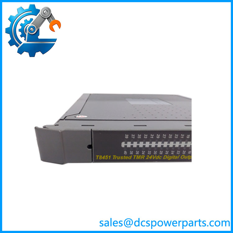
T8451
Application Scenarios & Field Pitfalls — The Engineer’s Perspective
Engineering Pain Point
A digital output that refuses to energize in a safety system cannot automatically be blamed on the . Field power, output wiring, the connected solenoid or relay, termination assembly, module configuration, and the Trusted processor all participate in the final control path. Because the actively monitors field current and voltage, its diagnostic information should be reviewed before replacing the module.
Typical Applications
1. Emergency shutdown systems
The can drive discrete field devices associated with shutdown and protective control functions where fault tolerance is required.
2. Solenoid and trip-device control
The 24 VDC outputs are suitable for compatible solenoid valves, trip relays, and other discrete field loads within the permitted electrical limits.
3. Burner and process protection
Trusted digital outputs can be used where discrete commands must be generated and monitored within a safety-instrumented architecture.
4. High-integrity industrial control
The TMR architecture makes the module appropriate for applications where a single internal output fault should not unnecessarily compromise system availability or safety behavior.
Technical Pitfalls
TMR is implemented within the module.
The does not simply provide three independent sets of conventional outputs. Its triplicated sections feed an internal safety-layer voter, with each output channel using a voted switching arrangement.
Do not confuse logical output state with actual field state.
The Trusted system can determine output status using measured voltage and current. This is important when diagnosing an apparently healthy command with an open field circuit or failed load.
Respect the group current limitation.
Although an individual channel is rated for up to 2 A continuous under the documented conditions, each eight-channel power group has an 8 A limit. The total load must therefore be evaluated at both the channel and group level.
Check the field load before replacing the module.
A shorted solenoid, damaged cable, or incorrect load can activate output protection. Replacing the without correcting the field-side problem can result in another protection event.
Pay attention to line-monitoring configuration.
Automatic line monitoring can detect open and short circuits, but the behavior depends on the connected load and application wiring. Field-device characteristics should be considered when interpreting diagnostics.
Use the correct Trusted termination arrangement.
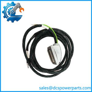
The is keyed to prevent installation in an incompatible position or with an incorrectly keyed field cable. The manufacturer documentation specifically identifies keying requirements for this module.
Do not substitute a different Trusted DO module based only on channel count.
Trusted modules can differ in voltage, architecture, output characteristics, diagnostics, and application certification. A 40-channel or 24 VDC description alone does not establish interchangeability.
Verify the exact module revision.
For a safety-system spare, compare the module label, hardware revision, firmware requirements, system configuration, and associated termination hardware with the installed unit before replacement.
Related Products
- ICS Triplex T8451C — coated/harsh-environment version where applicable; verify exact system approval and revision.
- ICS Triplex T8461 — different Trusted digital-output architecture; not an automatic drop-in substitute for .
- ICS Triplex T8403 — Trusted digital input module family.
- ICS Triplex T8431 — Trusted digital input hardware for compatible applications.
- ICS Triplex T8310 — Trusted TMR processor module.
- ICS Triplex T8100 — Trusted controller chassis family.
- ICS Triplex T8300 — Trusted expander chassis family.
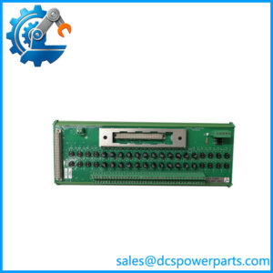
- ICS Triplex T8842 — Trusted field termination hardware family.
- ICS Triplex TC-303 — Trusted communication/expander cable family.
Procurement Note
For a replacement, verify the complete module designation, hardware revision, termination assembly, field cable/keying, Trusted chassis position, and system configuration. Do not treat it as a conventional PLC digital-output card.
For used industrial automation inventory, inspect the front-panel indicators, connector area, enclosure, PCB condition, and evidence of overheating or field-side overcurrent. A meaningful functional test should verify module diagnostics and representative output operation with the correct Trusted termination hardware and a controlled test load.
The critical identification is ICS Triplex Trusted — 40-channel TMR 24 VDC digital output module. Its distinguishing characteristics are TMR output architecture, five 8-channel power groups, field line monitoring, and 1 ms SOE reporting.