Description
Product Overview
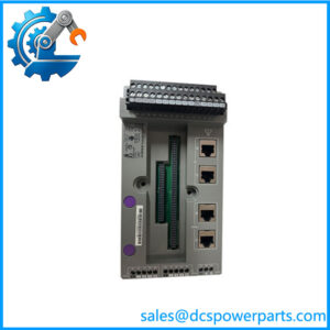
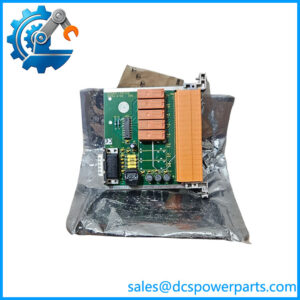
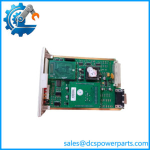
The Honeywell FC-IOCHAS-0002R is a redundant I/O chassis designed for the Safety Manager A.R.T. safety system. It provides the physical mounting structure and internal interconnection arrangement for up to 18 I/O modules, organized into nine redundant pairs. The chassis is a key part of the distributed I/O architecture: it accommodates the I/O backplane, horizontal I/O bus, transfer board, and extender modules required by the system configuration. It is therefore more than an empty rack enclosure; its internal hardware and interconnections are relevant to system availability and correct module operation.
The FC-IOCHAS-0002R assembly is documented with an I/O backplane identified as IOB-0002R, two FC-IO-0002 extender modules, an FC-IOBUS-HB2R horizontal I/O bus backplane, and an FC-IOBUS-HB2A transfer board installed behind the blind front at slot 19. Slots 1 through 18 accommodate the I/O modules, while slots 20 and 21 are allocated to the extender modules. This arrangement supports redundant I/O installation and the internal bus connections needed by the Safety Manager A.R.T. architecture.
For replacement procurement, the Honeywell FC-IOCHAS-0002R must be checked as a complete assembly. A chassis supplied without its backplane, bus boards, extender modules, or transfer board may not represent the same configuration as the original installed unit. The hardware reference specifies a 19-inch rack width, 280 mm depth, and 8.7 kg weight. Confirm the included internal components, connector condition, mounting arrangement, and applicable hardware revision before approving a replacement.
Product Introduction (Non-Templated)
A redundant safety I/O installation depends on more than the individual I/O cards. The chassis backplane and horizontal bus provide the physical connections that allow the installed module pairs and associated system hardware to operate as a configured assembly. Missing or damaged internal boards can turn an apparently correct replacement rack into an incomplete installation.
When sourcing FC-IOCHAS-0002R, compare the installed assembly against its component list. In particular, check the IOB-0002R backplane, IOBUS-HB2R, IOBUS-HB2A, and both IO-0002 extender modules. Do not approve a bare mechanical enclosure as a complete chassis replacement without confirming the required hardware.
Key Technical Specifications
| Parameter | Specification |
|---|---|
| Product Model | FC-IOCHAS-0002R |
| Manufacturer | Honeywell |
| System | Safety Manager A.R.T. |
| Product Type | Redundant I/O chassis |
| Chassis Format | 19-inch rack |
| Total Slot Positions | 21 |
| I/O Module Positions | 18, arranged as 9 redundant pairs |
| Transfer Board Position | Slot 19 |
| Extender Module Positions | Slots 20 and 21 |
| I/O Backplane | IOB-0002R |
| Horizontal I/O Bus | IOBUS-HB2R |
| Transfer Board | IOBUS-HB2A |
| Extender Modules | 2 × FC-IO-0002 |
| 5V-1 Consumption | 100 mA, slot 20 |
| 5V-2 Consumption | 100 mA, slot 21 |
| Width | 482.6 mm (19 in) |
| Depth | 280 mm (11 in) |
| First Chassis Height | 222.4 mm (8.75 in) |
| Additional Chassis Height | 177.8 mm (7 in) |
| Weight | 8.7 kg (19.2 lb) |
| Approvals | CE, UL, CSA, TÜV, FM; confirm applicable hardware-reference revision |
| Operating Temperature | Not verified |
| IP Rating | Not verified |
The height figures reflect the hardware-reference description: the first chassis includes the additional upper and lower sections, while subsequent chassis use a 4U height. Approval listings differ between document revisions, so verify the applicable certification status for the specific assembly.
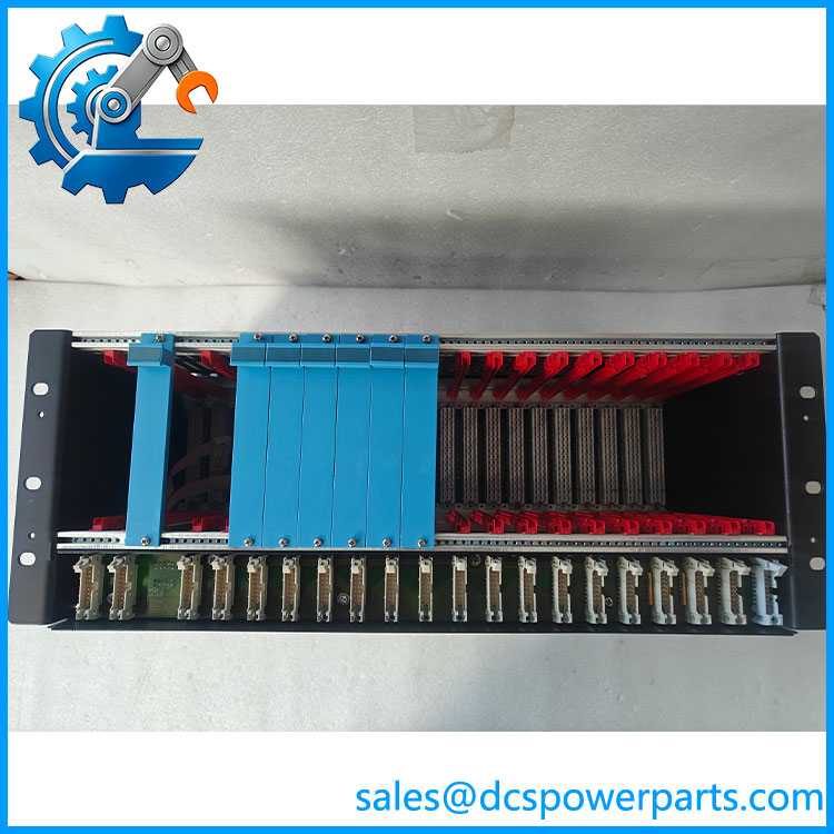
FC-IOCHAS-0002R
Major Features and Advantages
Support for redundant I/O pairs
The chassis accommodates up to 18 I/O modules in nine redundant pairs. This physical arrangement is intended for Safety Manager A.R.T. installations where redundant I/O hardware is part of the system design.
Integrated I/O backplane
The IOB-0002R backplane provides the module mounting and electrical interconnection structure. Its condition and connector integrity are important during replacement because damage can affect multiple installed I/O positions.
Horizontal I/O bus architecture
The FC-IOBUS-HB2R provides the horizontal bus arrangement. Its associated FC-IOBUS-HB2A transfer board is mounted at slot 19 behind the blind front. Both components should be checked when inspecting a complete chassis assembly.
Dedicated extender module positions
Slots 20 and 21 accommodate the FC-IO-0002 extender modules. The hardware reference specifies 100 mA consumption on each respective 5V rail for these positions. Verify that both extender modules are present and correctly seated.
Standard 19-inch rack installation
The 482.6 mm chassis width supports installation in a standard 19-inch equipment rack. The 280 mm depth and first-chassis height should be considered when checking cabinet clearance, cable routing, and adjacent equipment.
Documented assembly configuration
The manufacturer’s hardware reference identifies the main chassis components and their installation positions. This gives maintenance teams a component-level checklist when inspecting a replacement or assessing an incomplete assembly.
Related Products
The following components belong to or are associated with the Safety Manager redundant I/O architecture. They are related system hardware, not automatic substitutes for the complete chassis.
- IOB-0002R – Redundant I/O backplane used in the FC-IOCHAS-0002R assembly.
- FC-IO-0002 – I/O extender modules installed in chassis slots 20 and 21.
- FC-IOBUS-HB2R – Horizontal I/O bus backplane for redundant I/O.
- FC-IOBUS-HB2A – Horizontal I/O bus transfer board installed at slot 19.
- FC-IOCHAS-0001S – Separate Safety Manager I/O chassis configuration; verify system compatibility.
- FC-TSDI-1624 – Safety Manager digital input module.
- FC-TSDO-0824 – Safety Manager digital output module.
- FC- – Complete redundant I/O chassis assembly.
The chassis component relationships are documented in the Safety Manager Hardware Reference. Confirm the exact hardware revision and system release before combining components from different assemblies.
Frequently Asked Questions
Q1: What is the Honeywell FC- used for?
It is a redundant I/O chassis for the Honeywell Safety Manager A.R.T. system. It houses up to 18 I/O modules in nine redundant pairs and provides the associated backplane and bus interconnections.
Q2: How many I/O modules can the FC- accommodate?
It provides 18 I/O module positions, arranged as nine redundant pairs. The remaining positions are assigned to the transfer board and two I/O extender modules.
Q3: Is FC- supplied with its internal boards and extender modules?
The documented assembly includes the IOB-0002R backplane, two FC-IO-0002 extender modules, FC-IOBUS-HB2R, and FC-IOBUS-HB2A transfer board. However, actual supplied contents depend on the specific item being procured. Request an inventory and photographs before ordering.
Q4: Can I hot-swap the FC-?
Do not assume that the complete chassis can be hot-swapped. Removing or replacing it may affect multiple I/O modules and the system bus. Follow the approved Safety Manager shutdown, isolation, redundancy, and maintenance procedures.
Q5: Does FC- support firmware v3.1?
The chassis is passive mounting and interconnection hardware rather than a standalone firmware-controlled processor. Firmware compatibility is primarily relevant to the installed controller, extender modules, I/O modules, and Safety Manager system release. Verify the complete configuration against the applicable system documentation.
Q6: What should be checked when purchasing a replacement chassis?
Inspect the backplane connectors, horizontal bus boards, extender modules, slot condition, cable entry area, mounting points, and protective covers. Confirm that the assembly matches the original part number and component configuration.
Q7: Are the approvals identical across all FC- documentation revisions?
Not necessarily. Some hardware-reference records list FM as pending, while a later reference lists CE, UL, CSA, TÜV, and FM. Check the relevant document revision and certification records for the exact assembly being installed.
Procurement and Quality Control Notes
For Honeywell FC-, the main purchasing risk is receiving an incomplete or incorrectly configured chassis rather than the expected redundant I/O assembly.
Before shipment, request:
- Photographs of the complete chassis and identification label.
- Confirmation of the FC- part number.
- Confirmation that the backplane is included.
- Confirmation that both FC-IO-0002 extender modules are present.
- Inspection of the FC- and FC- boards.
- Close-up photographs of slot connectors and bus connections.
- Confirmation of hardware revision and any repair history.
- Written condition classification and warranty terms.
Engineering recommendation: Specify FC- as a complete, component-verified assembly when that is what the installed system requires. A matching chassis number alone does not establish that all internal boards and extender modules are included or serviceable.