Description
Key Technical Specifications
| Parameter | 05704-A-0121 | 05704-A-0131 |
|---|---|---|
| Manufacturer | Honeywell Analytics / Zellweger | Honeywell Analytics / Zellweger |
| System | System 57 / 5704 | System 57 / 5704 |
| Product Type | Quad Relay Interface Card | Relay Interface Assembly |
| Primary Function | Connects detector/transmitter loops to control card | Expanded detector-loop relay interface |
| Relay Configuration | 4 × SPCO | 12 × SPCO + 4 × SPST |
| Relay Operation | Latching / Non-latching; Energized / De-energized | Latching / Non-latching; Energized / De-energized |
| Contact Rating | 5 A at 110/250 VAC, non-inductive | 5 A at 110/250 VAC, non-inductive |
| DC Contact Rating | 5 A at 32 VDC, non-inductive | 5 A at 32 VDC, non-inductive |
| Typical Power | 1 W | 3.5 W |
| Maximum Power | 1.7 W | 6.5 W |
| Field Terminals | 2.5 mm² / 14 AWG | 2.5 mm² / 14 AWG |
| Approx. Dimensions | 132 × 25 × 119 mm | 132 × 52 × 122 mm |
| Approx. Weight | 230 g | 500 g |
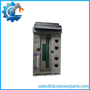
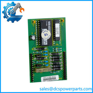
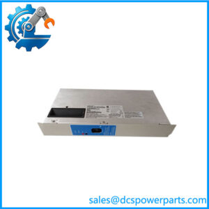
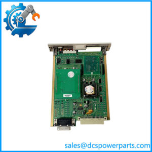
Honeywell’s System 57 manual specifies 05704-A-0121 as a Quad Relay Interface Card with four SPCO relays. The same documentation specifies 05704-A-0131 as a Relay Interface Assembly consisting of an expansion relay card fitted to the quad relay interface card, giving 12 SPCO and 4 SPST relays.
The relay contacts are specified for 5 A at 110/250 VAC or 32 VDC for non-inductive loads. The interface is intended to connect detector loops and the System 57 control electronics; it is not a general-purpose PLC output card.
Application Scenarios & Pain Points
Gas detection systems are unforgiving about relay wiring. A detector can report the correct gas concentration while the external shutdown circuit remains ineffective because a relay contact is miswired, a normally-open/normally-closed convention has been changed, or the wrong interface assembly has been installed.
- Fire and gas detection: The 05704-A-0121 connects detector/transmitter signals with the System 57 control architecture and provides four relay outputs for external alarm or control functions.
- Plant alarm management: Relay contacts can be assigned to alarm, fault, inhibit, or other System 57 functions depending on the installation configuration.
- Expanded alarm systems: 05704-A-0131 adds the expansion relay section, providing 16 relay contacts—12 SPCO and 4 SPST—for installations requiring more external relay functions.
- Gas detector interface cabinets: The cards can connect detector loops from compatible System 57 sensors and transmitters to the central control circuitry.
Field note: On a safety-related relay card, do not rely on wire color alone. Trace the actual terminal number and confirm the contact state against the approved drawing. A swapped NO/NC connection can remain invisible until the exact alarm condition occurs.
Brief Field Case
During replacement of an older 5704 cabinet, a relay assembly may appear to have the same connector arrangement while carrying a different number of external contacts. The correct approach is to photograph the existing card, record each terminal, and compare the relay count before removing anything.
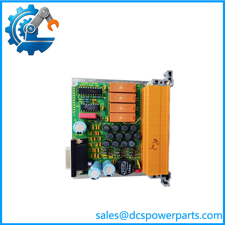
05704-A-0121
Related Products
- Honeywell 05704-A-0121 — Quad Relay Interface Card with four SPCO relays. Best suited to the standard four-channel relay interface arrangement.
- Honeywell 05704-A-0131 — Expanded Relay Interface Assembly. Combines the quad relay interface with an expansion relay card, providing 12 SPCO plus 4 SPST relays.
- Honeywell 05704-A-0122 — The user-supplied identifier. It should be verified against the physical label and System 57 documentation before being treated as an independent catalog number.
- Honeywell 05704-A-0130 — Related expansion relay hardware within the System 57 5704 relay-interface architecture; useful when rebuilding or servicing an expanded relay arrangement.
- Honeywell 05701-A Series — System 57 detector/control modules that work at the detector and control-card level rather than serving as direct relay-interface replacements.
- Honeywell System 57 5704 Control System — The parent control platform for these relay-interface assemblies. The 05704 cards should be selected according to the installed cabinet architecture, detector type, and approved wiring drawings.
- Honeywell System 57 detector modules — Compatible detector/control components used upstream of the relay interface. They provide the sensing/control information that the relay assembly ultimately exposes to external circuits.
- Honeywell Digi-Cat / Digi-Chem / Digi-Ana interfaces — Detector/transmitter connection types documented for the 05704-A-0121 installation wiring. Sensor type and terminal assignment must be checked before replacement.
The Engineer’s Guide: Field Pitfalls to Avoid
WARNING 1 — Do not confuse 05704-A-0121 with 05704-A-0131.
They are related but have substantially different relay capacity. 05704-A-0121 has 4 SPCO relays, while 05704-A-0131 has 12 SPCO + 4 SPST relays.
How to avoid it: Count the physical relay functions and compare the existing cabinet drawing before ordering. Do not substitute based on the “05704” prefix alone.
WARNING 2 — Verify NO/NC and energized/de-energized logic.
The relay operation is configurable, including latching/non-latching and energized/de-energized operation.
How to avoid it: Document the existing relay state under normal operation and alarm/fault conditions before disconnecting the card. For safety circuits, verify the intended fail-safe state against the approved control drawing.
WARNING 3 — Treat 05074-A-0122 as an identification requiring verification.
The System 57 documentation I found clearly identifies 05704-A-0121 and 05704-A-0131, but I did not find authoritative documentation establishing 05074-A-0122 as the standard catalog number for this assembly.
How to avoid it: Photograph the label and terminal layout. If the actual marking is 05704-A-0122, record that exact number; if it really reads 05074-A-0122, obtain the equipment drawing or original BOM before purchasing.
Frequently Asked Questions (FAQ)
What is Honeywell 05704-A-0121?
05704-A-0121 is the System 57 Quad Relay Interface Card. It provides connections between detector/transmitter loops and the control card and contains four SPCO relay outputs.
It is therefore a dedicated gas-detection-system interface rather than a conventional PLC relay output module.
What is Honeywell 05704-A-0131?
05704-A-0131 is the System 57 Relay Interface Assembly. It combines an expansion relay card with the Quad Relay Interface Card. The resulting assembly provides 12 SPCO and 4 SPST relays.
That makes it suitable when the cabinet requires more external alarm/control relay functions than the basic 05704-A-0121 can provide.
Can 05704-A-0131 replace 05704-A-0121?
Not as a simple one-for-one substitution. The 0131 is an expanded assembly with a different relay arrangement, dimensions, power consumption, and wiring requirements.
Before substitution, compare:
- Relay quantity
- SPCO/SPST configuration
- Terminal wiring
- Cabinet space
- Alarm logic
- External circuit requirements
What is the relay contact rating?
The System 57 documentation specifies 5 A at 110/250 VAC for non-inductive loads and 5 A at 32 VDC for non-inductive loads.
Do not apply the maximum current rating blindly to motors, solenoids, contactors, or other strongly inductive loads. Their switching characteristics can be very different from the stated non-inductive rating.
How much power does 05704-A-0121 consume?
The documented figures are approximately 1 W typical and 1.7 W maximum. The expanded 05704-A-0131 assembly is specified at approximately 3.5 W typical and 6.5 W maximum.
The difference is relevant when checking the cabinet’s 24 VDC power budget.
What sensors can connect to the 05704-A-0121?
The System 57 installation documentation shows wiring arrangements for several detector/transmitter types, including Digi-Cat, Digi-Chem, Digi-Ana, catalytic, and ECC-related configurations, with channel-specific terminal assignments.
Do not assume that every System 57 detector uses the same wiring. Verify the exact detector model and approved wiring diagram before connecting a replacement card.
What should I request when purchasing a replacement?
For a production gas-detection system, request:
- Exact part-number photograph.
- Front and rear photographs.
- Relay count and type.
- Terminal-block condition.
- Relay contact functional test.
- Energized/de-energized operation test.
- Latching/non-latching verification.
- Detector-loop interface test where applicable.
- Written warranty.
- Test report.
For 05704-A-0131, specifically confirm that the assembly contains the expected 12 SPCO + 4 SPST relay configuration rather than assuming that a visually similar System 57 relay card is equivalent.