Description
Product Overview
The Woodhead SST-PB3-CLX is a PROFIBUS DP scanner module designed to connect an Allen-Bradley ControlLogix controller with field devices on a PROFIBUS network. Installed in a compatible ControlLogix chassis, it provides a communication interface between the controller’s backplane and one PROFIBUS network segment. Typical connected equipment includes distributed I/O stations, motor drives, process instrumentation, and other PROFIBUS-compatible devices. This arrangement allows a ControlLogix-based automation system to exchange cyclic process data with field equipment that uses the PROFIBUS protocol.
The SST-PB3-CLX supports PROFIBUS DP master and slave functionality, with documented support for DP-V0 and DP-V1 master operation and DP-V0 slave operation. Its single PROFIBUS interface uses an isolated RS-485 connection through a 9-pin female D-sub connector. The documented communication speed range is 9.6 kbps to 12 Mbps. Configuration and diagnostic functions are provided through the module’s configuration interface and associated engineering tools.
In maintenance and system-integration projects, the SST-PB3-CLX should be evaluated as a network-interface component rather than a standard digital or analog I/O card. The module’s firmware, configuration file, PROFIBUS node addresses, baud rate, and controller-side data mapping all affect successful commissioning. The RLL variant also has a specific software-library association, so buyers should distinguish the base model from SST-PB3-CLX-RLL, SST-PB3-CLX-DTM, and other ordering variants. Before replacing an installed unit, preserve its configuration and verify the required software tools and ControlLogix compatibility.
Product Introduction
A PROFIBUS network fault can interrupt data exchange with multiple remote devices even when the ControlLogix processor remains in RUN mode. The scanner module is therefore a critical point to inspect when diagnosing communication loss, missing remote I/O data, or inconsistent device status.
The SST-PB3-CLX provides one PROFIBUS DP interface for a ControlLogix system. Replacement planning should include the original module configuration, node-address assignments, network termination, and controller data mapping—not just the physical module number.
Key Technical Specifications
| Parameter | Specification |
|---|---|
| Model | |
| Manufacturer | Woodhead / SST (Molex) |
| Product Type | PROFIBUS DP Scanner |
| Controller Platform | Allen-Bradley ControlLogix |
| Installation | ControlLogix chassis |
| PROFIBUS Channels | 1 |
| Network Interface | RS-485 |
| Connector | 9-pin female D-sub |
| Electrical Isolation | 500 V galvanic isolation, per product datasheet |
| Baud Rate | 9.6 kbps to 12 Mbps |
| Network Protocols | PROFIBUS DP-V0 / DP-V1 |
| Master Operation | DP-V0 and DP-V1 |
| Slave Operation | DP-V0 |
| Configuration Interface | RS-232 serial port |
| USB Interface | USB 2.0 / 1.1, documented for associated engineering tools |
| Shared Memory | 512 KB |
| Flash Memory | 512 KB |
| Maximum Input Data | 1,984 bytes |
| Maximum Output Data | 1,968 bytes |
| Status Data | 250 words |
| Backplane Current | 850 mA at 5 VDC or 1.75 mA at 24 VDC |
| Operating Temperature | 0°C to 60°C |
| Storage Temperature | -40°C to 85°C |
| Certifications | CE, RoHS, Class I Division 2 Groups A, B, C, D, according to datasheet |
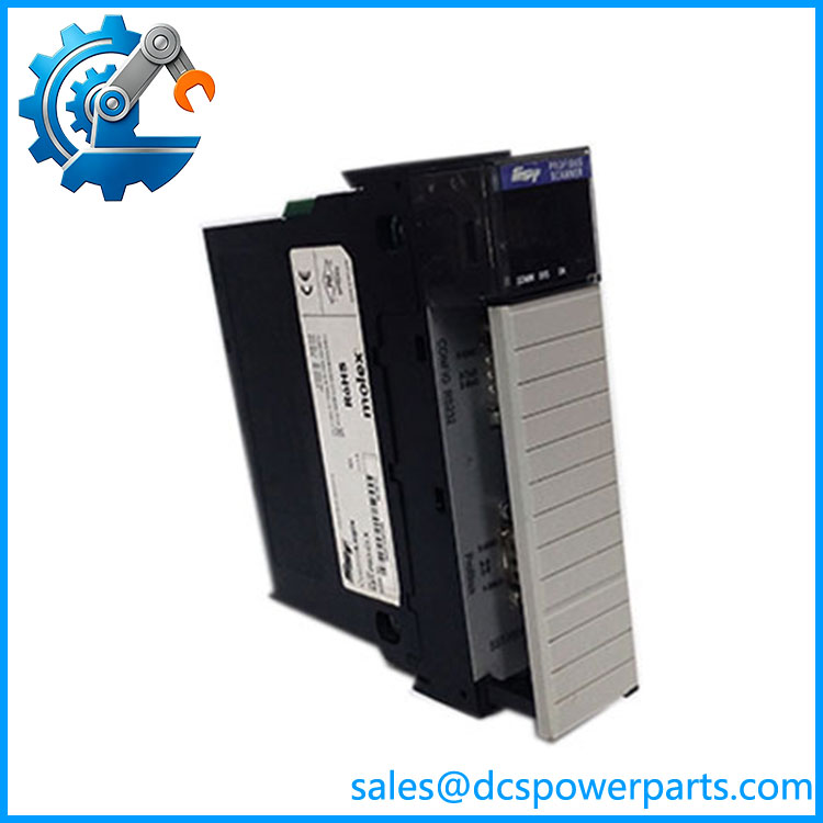
SST-PB3-CLX
Major Features and Advantages
ControlLogix chassis integration
The module installs in a compatible ControlLogix chassis and provides a PROFIBUS interface for controller-to-field-device communication. This is useful when a plant needs to retain PROFIBUS equipment while using ControlLogix as its main controller platform.
PROFIBUS DP master and slave capability
The scanner supports master and slave operating modes. The required mode depends on the network architecture and the role assigned to the ControlLogix system. Confirm the intended operating mode before configuring the module.
Single isolated RS-485 network interface
One 9-pin female D-sub connector provides the PROFIBUS connection. The documented 500 V galvanic isolation helps separate the network interface electrically from the module’s internal circuitry. Proper cable shielding, grounding, and termination remain necessary.
Wide PROFIBUS baud-rate range
The supported range of 9.6 kbps to 12 Mbps accommodates different PROFIBUS network designs. The actual operating rate must be consistent across the network and supported by all connected devices.
Large data-mapping capacity
The product datasheet lists up to 1,984 input bytes and 1,968 output bytes, with 250 words of status data. These limits are important when planning remote I/O allocation and controller-side data structures. The usable amount may also depend on configuration and system software.
Configuration and diagnostic access
The module supports configuration and diagnostic tools through its documented interfaces. The four-character scrolling display and COMM, SYS, and OK indicators help maintenance personnel identify network health, communication status, and initialization state.
Related Products
- -RLL – ControlLogix PROFIBUS scanner variant supplied with Remote Link Library.
- -RLL-CC – Coated version of the RLL scanner variant.
- -DTM – Scanner package associated with a CommDTM driver license.
- -DTS – CommDTM update driver license for the PROFIBUS scanner.
- SST-PBF-CLX – Earlier PROFIBUS interface model for ControlLogix applications.
- SST-PBF-CLX-RLL – Earlier ControlLogix PROFIBUS scanner variant.
- SST-PB3-MOD – Related SST PROFIBUS scanner family member; verify controller platform before considering it.
These are related product or software designations, not guaranteed hardware substitutes.
Frequently Asked Questions
Q1: What is the used for?
It connects an Allen-Bradley ControlLogix controller to PROFIBUS DP field devices. It is commonly used for communication with remote I/O stations, drives, and other PROFIBUS-compatible equipment.
Q2: Does the support PROFIBUS DP-V1?
Yes. The product datasheet lists DP-V0 and DP-V1 Class 1 and Class 2 master support, as well as DP-V0 slave support.
Q3: Can I hot-swap the ?
Do not assume that powered removal is permitted. Follow the ControlLogix chassis and module installation instructions, and verify the project’s approved maintenance procedure. Isolate the affected network and process functions before removal unless the applicable documentation explicitly permits online replacement.
Q4: Does the support firmware v3.1?
A specific firmware v3.1 compatibility statement has not been verified. Check the installed module firmware, configuration utility, controller software, and associated library versions before updating or replacing the scanner.
Q5: Can replace -RLL?
Not necessarily as a complete software package. The RLL suffix identifies a version associated with the Remote Link Library. Confirm the existing application dependencies and required software components before substituting the base model.
Q6: What causes PROFIBUS communication failure with this module?
Common areas to investigate include incorrect node addresses, inconsistent baud-rate settings, missing or incorrect bus termination, cable faults, shielding and grounding problems, incompatible GSD configuration, and module configuration errors. Review the COMM and SYS indicators along with the network diagnostics.
Q7: How should a replacement be tested?
Verify ControlLogix chassis recognition, module initialization, PROFIBUS network status, master or slave operation, and communication with representative field devices. Check input and output data mapping against the original configuration. Preserve the existing configuration before commissioning the replacement.
Procurement and Quality Inspection Notes
Before purchasing an , confirm:
- Exact model and suffix.
- Compatibility with the installed ControlLogix chassis.
- Required master or slave operating mode.
- PROFIBUS DP-V0 / DP-V1 requirements.
- Existing Remote Link Library or CommDTM dependencies.
- Firmware and configuration-tool compatibility.
- Condition of the 9-pin D-sub connector.
- COMM, SYS, and OK indicator operation.
- PROFIBUS communication test results.
- Input/output data mapping verification.
- Firmware and configuration backup availability.
Lifecycle note: The is an older Woodhead/SST product family, and some product records identify it as discontinued. Confirm current manufacturer support status and plan to preserve the existing configuration, software dependencies, and a tested spare where continued operation is required.