Description
GE Fanuc VMIVME-7807RC | Pentium M VMEbus SBC | 6U Industrial Computer
Key Technical Specifications
| Parameter | Specification |
|---|---|
| Manufacturer | GE Fanuc Embedded Systems / VMIC |
| Model | VMIVME-7807RC / VME-7807RC |
| Product Type | VMEbus Single Board Computer |
| Form Factor | 6U VME Eurocard |
| VME Slots | 1 |
| Processor | Intel Pentium M |
| Processor Options | 1.1, 1.4, 1.6/1.8 GHz depending configuration |
| Chipset | Intel 855GME |
| System Bus | 400 MHz |
| Memory | Up to 1.5 GB DDR SDRAM |
| CompactFlash | Up to 2 GB, optional |
| PMC | 1 × PCI-X, 66 MHz |
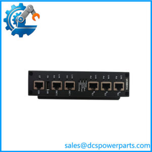
| Ethernet | 10/100 + dual Gigabit Ethernet |
| USB | 4 × USB 2.0 |
| Serial | 4 × asynchronous serial ports |
| Video | Front SVGA + rear DVI-D |
| VME Interface | VMEbus via Tundra Universe II |
| Watchdog | Software-selectable watchdog timer |
| Operating Systems | Windows, Linux, VxWorks, Solaris, QNX and others |
The VMIVME-7807/VME-7807RC documentation specifies a Pentium M processor, Intel 855GME chipset, up to 1.5 GB DDR SDRAM, dual Gigabit Ethernet, one 10/100 Ethernet interface, four USB 2.0 ports, four serial interfaces, and one PCI-X 66 MHz PMC expansion site.
The Abaco product documentation for the V7807RC confirms the 6U VME form factor, one expansion slot, Tundra Universe II VME interface, up to 1.5 GB DDR SDRAM, Gigabit Ethernet, four serial I/O channels, and compatibility with VMIACC-0586 and VMIACC-0590 transition modules.
Product Introduction
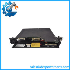
The GE Fanuc VMIVME-7807RC is a Pentium M-based 6U VMEbus single-board computer intended for embedded computing, industrial control, instrumentation, simulation, data acquisition, and process-control applications. Its single-slot architecture combines processor, memory, Ethernet, serial communication, USB, video, storage interfaces, and PMC expansion on one VME board.
The board can operate as either a VME system controller or a peripheral, depending on the system configuration. Rear I/O is handled through compatible transition modules, making the exact RTM and backplane arrangement important when replacing a board in an existing installation.
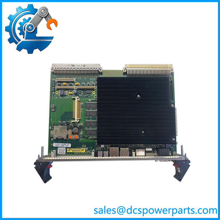
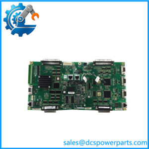
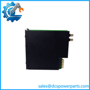
VMIVME-7807RC
Application Scenarios & Field Pitfalls — The Engineer’s Perspective
Engineering Pain Point
A legacy VME computer can fail in ways that initially look like a backplane, operating-system, or application problem. With the VMIVME-7807RC, memory configuration, BIOS/flash condition, CompactFlash media, PMC hardware, rear transition module, and VMEbus system-controller settings all need to be considered before declaring the SBC itself defective.
Typical Applications
- Industrial VME control computers
- Process-control and monitoring systems
- Factory automation equipment
- Data-acquisition systems
- Automated test equipment
- Simulation and instrumentation platforms
- Telecommunications embedded systems
The original GE Fanuc documentation specifically lists telecommunications, simulation, instrumentation, industrial control, process control and monitoring, factory automation, automated test, and data acquisition among the intended application areas.
Technical Pitfalls
- Do not confuse VMIVME-7807RC with VMIVME-7750.
The 7807RC is based on the Pentium M / 855GME architecture, while the VMIVME-7750 belongs to an earlier Pentium III generation. A similar 6U VME mechanical format does not make the boards interchangeable. - Verify the exact processor configuration.
The 7807 family was offered with different Pentium M speeds. Do not assume that every VMIVME-7807RC contains the same CPU frequency. Procurement should record the complete ordering code or board label. - Memory configuration matters.
The documented architecture supports one SODIMM plus optional soldered memory, with a maximum configuration of 1.5 GB. A replacement with a different memory configuration may affect an older operating-system image or application environment. - Check the rear transition module.
GE Fanuc specifies VMIACC-0586/ACC-0586RC and VMIACC-0590/ACC-0590RC as compatible rear transition hardware. If the existing installation depends on rear I/O, replacing the SBC without checking the RTM can leave required interfaces inaccessible. - VME system-controller position must be preserved.
The board can operate as a system controller or peripheral. Its slot position and VMEbus configuration therefore need to match the original chassis design. - Do not overlook CompactFlash.
Optional CompactFlash can be configured as a boot device. If the original system boots from CompactFlash, preserve the media image and verify BIOS boot-device settings before replacing the SBC. - PMC compatibility is system-dependent.
The board provides one PCI-X 66 MHz PMC site. The installed PMC module can be essential to the application’s function, so its power, rear-I/O, driver, and operating-system requirements should be checked separately. - Passive cooling does not mean unrestricted thermal operation.
The 7807RC uses a passively cooled VME form factor. Chassis airflow and adjacent-board spacing remain important, particularly when the CPU and PMC are under sustained load.
Related Products
- VMIVME-7807 — Closely related Pentium M VME SBC; compare exact configuration and ordering code before substitution.
- VME-7807RC — Equivalent family designation for the hardware.
- V7807RC — Abaco Systems designation for the same VME-7807RC product family.
- VMIVME-7750 — Earlier Pentium III VME SBC; similar application class but different processor and chipset architecture.
- VMIACC-0586 / ACC-0586RC — Compatible rear transition module family.
- VMIACC-0590 / ACC-0590RC — Alternative rear transition module family for installations.
- PMC modules — PCI-X mezzanine cards that can occupy the board’s single PMC expansion site.
- VMIVME VME chassis/backplanes — Host hardware requiring correct slot, system-controller, power, and rear-I/O configuration.
Procurement Note
For a replacement , do not specify only “Pentium M VME board.” Record the complete board ordering code, processor speed, installed memory, CompactFlash configuration, PMC module, RTM type, and VME system-controller role.
For a used or refurbished board, inspect the VME connector pins, PMC connector, memory socket, CompactFlash interface, front Ethernet ports, rear-I/O connections, battery/RTC condition, and heatsink assembly. Before putting the spare into a live chassis, verify the BIOS configuration and confirm that the existing operating-system/application image can run on the replacement hardware.
The model is now legacy hardware, so keeping a tested spare with a preserved boot image and documented BIOS settings is often more practical than trying to reconstruct the software environment after the installed SBC fails.