Description
Product Introduction
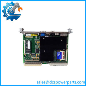
When a legacy control computer loses discrete signal visibility or cannot drive an external control circuit, replacing the I/O board with a correctly configured unit can help restore operation without redesigning the entire system. The GE Fanuc VMIVME-2536 provides 32 isolated digital inputs and 32 isolated digital outputs in a VMEbus-compatible board format.
Its built-in test functions support diagnostic checks, while configurable input sensing and byte-level jumper settings allow the board to suit different field wiring arrangements. For a VMIVME-2536 replacement, verify the input-voltage option, jumper configuration, connector wiring, and software-level VME addressing before installation.
Key Technical Specifications
| Parameter | Specification |
|---|---|
| Model | VMIVME-2536 |
| Manufacturer lineage | GE Fanuc / VMIC; now listed by Abaco Systems |
| Board type | Digital input/output board |
| Form factor | 6U VMEbus Eurocard |
| Digital inputs | 32 optically coupled inputs |
| Digital outputs | 32 optically coupled outputs |
| Input voltage range | 5–125 VDC, depending on ordered option |
| Output type | Optically isolated open-collector, current-sinking |
| Maximum output current | 300 mA |
| Maximum output voltage | 50 V |
| Field-to-backplane isolation | 1 kV sustained |
| Data transfer widths | 8, 16, and 32 bits |
| Addressing | A16 or A24, depending on configuration |
| Input sensing | Voltage sensing or contact sensing |
| Built-in test | Online and offline BIT support |
| Field interface | Front-panel I/O through board connectors |
| Operating temperature | Commonly documented as 0 to +60°C; verify the applicable manual |
| Lifecycle status | Abaco lists the VME-2536 product as having entered Restricted Production Phase on April 1, 2021 |
Sources: Abaco product page, VMIVME-2536 manual, and datasheet.
Configuration note: The input voltage is option-dependent. The legacy ordering information distinguishes 5 V, 12 V, 24–28 V, 48 V, and 125 V sensing options; the 125 V option is for voltage sensing only. Confirm the installed board’s exact option and jumpers rather than assuming every VMIVME-2536 supports every input mode.
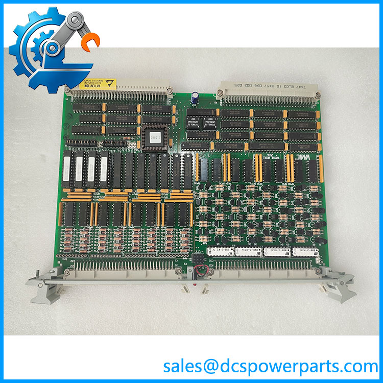
VMIVME-2536
Application Scenarios & Pain Points
A VME I/O replacement can fail at commissioning even when the board fits the chassis. Field voltage, jumper settings, output loading, and software addressing must all agree.
- Industrial control and data acquisition: Read discrete status signals from field devices through optically coupled inputs.
- Machine and process control: Drive compatible external loads through current-sinking digital outputs.
- Legacy VME computer systems: Maintain existing VMEbus hardware where changing the host computer or application software would be disruptive.
- System diagnostics: Use the onboard BIT capability to help isolate I/O faults during maintenance and troubleshooting.
In practice, record the original jumper positions and terminal wiring before removing the board. After installation, test inputs and outputs under an approved procedure, confirming the actual field signal states and load behavior.
Related Products
These related products are useful when maintaining legacy VMIC systems, but their functions and interfaces differ.
- VMIVME-2532A — Related VMEbus digital I/O product; compare channel architecture and electrical specifications before considering substitution.
- VMIVME-2536 — Exact model reference for like-for-like sourcing; verify the ordered input-voltage option.
- VME-2536 — Abaco’s current catalog naming for this product family; confirm the specific part identity and order code with the supplier.
- VMIVME-2535 — A different legacy VMIC board designation; verify the hardware function before evaluating it as an alternative.
- VMIVME-4140 — VMEbus analog output board; intended for analog rather than discrete I/O tasks.
- VMIVME-7750 — VMEbus computer-board family; a host-computing component, not a direct digital I/O substitute.
Important: A shared VMEbus form factor does not guarantee electrical, software, or functional interchangeability.
Engineer’s Guide: Three Replacement Checks
1. Match the field input option. Confirm whether the installed board is configured for 5 V, 12 V, 24–28 V, 48 V, or 125 V sensing. The wrong option can produce incorrect readings or expose the input circuitry to unsuitable field voltage.
2. Verify output loading and pull-up arrangements. The outputs are open-collector/current-sinking, not general-purpose voltage-sourcing outputs. Check load current, maximum voltage, external pull-up supply, and jumper settings. Do not connect a load based only on the 300 mA rating.
3. Check addressing, connectors, and startup behavior. Verify A16/A24 addressing, the required data width, front-panel cable termination, and the system’s software driver. The manual also notes that outputs require initialization before being placed online after power-up or reset.
Frequently Asked Questions
What is the GE Fanuc used for?
It is a VMEbus digital I/O board for reading and controlling discrete field signals. It provides 32 optically coupled inputs and 32 optically coupled outputs, along with built-in test functionality.
Does have 32 inputs or 32 outputs?
It has 32 inputs and 32 outputs. These are separate groups of optically coupled channels, so the board provides 64 I/O signal points in total.
Can I connect 24 VDC signals to this board?
The board family includes 24–28 V input options, but the installed option must be verified. Check the board’s order code and jumper configuration before connecting field wiring.
Are the outputs relay contacts?
No. The documented outputs are optically isolated open-collector/current-sinking outputs. They should not be treated as dry relay contacts or voltage-sourcing outputs. Verify the external circuit and pull-up arrangement before use.
What does built-in test do?
The board supports online and offline BIT functions for checking input and output behavior. In input test mode, onboard test-register data can be read in place of field input data; output test mode can disable the outputs while test patterns are checked. Follow the manual to avoid unintended field actions.
Is still in production?
Abaco lists the VME-2536 as having entered Restricted Production Phase on April 1, 2021. Confirm current availability and any recommended successor with the manufacturer or supplier before planning a long-term maintenance strategy.
What should I provide when requesting a quotation?
Provide the complete model number, input-voltage option, photos of the board label and connectors, required condition, and the intended VME system. Ask for confirmation of the exact option, test scope, warranty, and dispatch lead time.
Procurement recommendation: The key checks are the input-voltage option, output circuit requirements, and VME configuration. Match those against the installed board and manual before ordering a replacement.