Description
GE Multilin SR469-P5-HI-A20 | Motor Management Relay | 5A CT Protection
Key Technical Specifications
| Parameter | Specification |
|---|---|
| Manufacturer | GE Multilin |
| Product family | 469 Motor Management Relay |
| Exact model | SR469-P5-HI-A20 |
| Relay type | Motor protection and management relay |
| Phase CT input | 5 A secondary |
| Control power | 70–265 VAC, 48–62 Hz |
| DC control power | 90–300 VDC |
| Analog outputs | 4 × 4–20 mA |
| Communications | RS-232 / RS-485; Modbus RTU capability |
| Construction | Draw-out relay with separate case |
| Application | Industrial motor protection and monitoring |
| Front interface | Local display, keypad, status LEDs |
| Configuration software | EnerVista 469 Setup |
The P5 designation identifies the 5 A phase-current input configuration, while HI corresponds to the high-range control-power version. The A20 configuration provides four 4–20 mA analog outputs. The published identification data for the exact SR469-P5-HI-A20 also lists 70–265 VAC control power and Modbus RTU capability.
Product Introduction
The GE Multilin SR469-P5-HI-A20 is a dedicated motor management relay for industrial motor protection, measurement, control, and condition monitoring. It is intended for applications where protection functions and motor operating data need to be handled in one relay rather than divided between separate protective devices and PLC logic.
The 5 A phase-CT configuration makes the relay suitable for installations using 5 A CT secondaries. Four 4–20 mA outputs can be used to transmit selected motor measurements to a DCS, PLC, recorder, or other analog monitoring system.
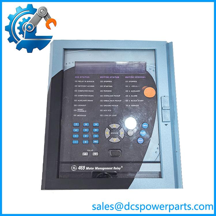
SR469-P5-HI-A20
Application Scenarios & Field Pitfalls — Engineer’s Perspective
Engineering Pain Point
With an older 469 relay, the primary replacement risk is ordering-code mismatch, not simply relay failure. P1 and P5 versions use different phase CT secondary configurations, while HI and LO versions have different control-power requirements.
Typical Applications
- Medium-voltage motor protection — Protection and monitoring of large pumps, compressors, fans, blowers, and process motors.
- Motor thermal management — Thermal modeling, overload protection, starting supervision, and abnormal operating-condition detection.
- Plant DCS integration — Four 4–20 mA outputs provide an analog path for selected operating measurements.
- Switchgear motor feeders — Integration with breaker/control circuits through the relay’s configurable outputs and protection logic.
Technical Pitfalls to Avoid
- Do not substitute a P1 relay for P5. The
P5configuration is associated with 5 A phase CT inputs. A 1 A CT installation requires the appropriate P1 configuration. - Do not assume
SR469-P5-HI-A20-Eis the same unit. The-Evariant is separately identified with enhanced functionality, including its specific control-power and display configuration. The baseSR469-P5-HI-A20should be matched exactly when maintaining an existing installation. - Do not assume the
-Tversion is interchangeable. The -T is identified with Ethernet capability, making it a different communications configuration. - Verify CT wiring before energization. A 5 A CT circuit should never be connected based only on the relay family name. Confirm phase CT ratios, polarity, grounding, and secondary wiring against the protection drawing.
- Preserve the existing settings. Motor FLA, service factor, acceleration time, thermal model, start limits, ground-fault settings, unbalance limits, RTD settings, and trip logic should be recorded before removing a failed relay.
- Check the case as well as the relay. GE documentation identifies separate permanent labels on the relay unit and case, with model information, control-power data, CT input, firmware, and output-contact information. Matching only the front-panel model is not sufficient for a critical replacement.
Related Products
- — Related 5 A / HI configuration with enhanced display/features; not automatically a drop-in equivalent.
- — 5 A / HI configuration with Ethernet capability; useful where Ethernet communications are required.
- — Enhanced-display version with conformal coating for harsher environments.
- GE Multilin SR469-P5-LO-A20 — 5 A phase CT configuration with lower-range control power; not a direct HI replacement.
- GE Multilin SR469-P1-HI-A1-E — 1 A phase-CT configuration; the CT input rating differs fundamentally from P5.
- GE Multilin SR465 — Related GE Multilin motor protection family, but it is a different relay platform and should not be treated as a functional drop-in replacement.
- GE Multilin 489 — Motor management relay family used in similar industrial applications, with a different hardware and protection architecture.
Procurement Note
For an replacement, verify these items against the installed relay before purchasing:
P5 phase CT rating → HI control power → A20 analog-output configuration → display option → communications hardware → firmware revision → case compatibility.
The biggest procurement mistake is accepting an SR469 family match while overlooking the suffix. The P5, HI, and A20 portions describe real hardware/configuration differences, and the -E or -T variants should be evaluated separately.