Description
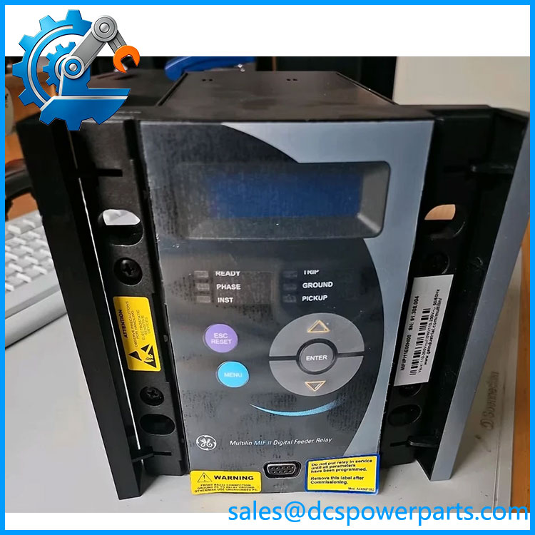
GE Multilin MIFIIPI11E00HI00
Product Overview
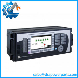
The GE Multilin MIFIIPI11E00HI00 is a member of the GE Multilin MIF II digital feeder protection family, designed for primary protection of distribution feeders and backup protection for equipment such as transformers, motors, and generators. The MIF II combines time-overcurrent, instantaneous overcurrent, thermal protection, metering, event recording, configurable logic, and communications in a dedicated feeder-protection relay rather than a general-purpose PLC. GE’s documentation describes the MIF II as a protection relay for distribution networks at any voltage level, with selected models supporting three-phase and ground protection.
For the GE Multilin MIFIIPI11E00HI00, the ordering code is important because it identifies the particular electrical and functional configuration. Available documentation identifies this model as a three-phase-plus-ground version using 1 A phase CT and 1 A ground CT inputs, with IEC protection curves, English language support, configurable I/O and LED functionality, no recloser option, a high-range power supply, and the standard Modbus RTU communications arrangement. A representative nameplate record for this exact model specifies 110–250 VDC / 10 W or 120–230 VAC / 30 VA, a maximum digital-input voltage of 300 VDC, and 1 A phase / 1 A ground analog current inputs.
In the field, the MIF II is most relevant when maintaining legacy switchgear where protection settings, CT ratios, trip logic, and communications already depend on the relay’s established configuration. It provides a front-panel LCD and keypad, status LEDs, local RS232 access, and rear RS485 communications. EnerVista MIF II Setup software is used for relay configuration and setting management. That means replacement is not simply a matter of matching the front-panel dimensions; the existing protection file and site settings should be recovered before removing the original relay.
Product Introduction
A feeder relay replacement becomes risky when the hardware is matched but the protection configuration is not. The GE Multilin MIFIIPI11E00HI00 is a 1 A phase / 1 A ground MIF II configuration with IEC curves, configurable I/O and LEDs, high-range control power, and Modbus RTU communications.
For a legacy feeder protection replacement, verify the complete ordering code, CT secondary rating, power supply, trip/close wiring, digital-input voltage, communication protocol, and stored protection settings before accepting another MIF II variant as equivalent.
Key Technical Specifications
| Parameter | Specification |
|---|---|
| Product Model | MIFIIPI11E00HI00 |
| Manufacturer / Brand | GE Multilin |
| Product Series | MIF II |
| Product Type | Digital Feeder Protection Relay |
| Application Configuration | Three-phase + ground |
| Phase CT Input | 1 A nominal |
| Ground CT Input | 1 A nominal |
| Protection Curve | IEC |
| Control Language | English |
| Configurable I/O / LEDs | Included |
| Recloser | Not included |
| Control Power | 110–250 VDC / 120–230 VAC configuration |
| Power Consumption | 10 W DC / 30 VA AC, as identified on representative nameplate |
| Digital Input Voltage | 300 VDC maximum for high-range supply configuration |
| Communication | Front RS232 and rear RS485 |
| Communication Protocol | Modbus RTU |
| Display | 16 × 2 character LCD |
| Keypad | 5-button front-panel keypad |
| Status LEDs | 6, with configurable LED functionality on applicable option |
| Mounting | Panel / switchgear relay mounting |
| Configuration Software | EnerVista MIF II Setup |
The exact model’s nameplate evidence supports the power-supply and CT-input figures above. Family-level MIF II documentation supplies the functional and communications information. Some online listings incorrectly assign specifications from other MIF II ordering codes to this model, so voltage, CT, recloser, and communications options should be checked against the complete ordering code rather than copied from a neighboring variant.
MIFIIPI11E00HI00
Major Features and Engineering Advantages
1. Dedicated Feeder Protection
The MIF II was designed specifically for feeder protection. Its basic protection package includes time-delayed overcurrent, instantaneous overcurrent, and thermal-image protection. Depending on the selected model and options, additional functions include breaker failure, breaker health monitoring, cold-load pickup, configurable logic, and autoreclosing.
2. 1 A Phase and Ground CT Configuration
The MIFIIPI11E00HI00 is specifically identified with 1 A phase and 1 A ground CT inputs. This is one of the most important ordering-code details when replacing a relay. A 5 A CT version is not automatically equivalent simply because it belongs to the same MIF II family.
3. IEC Overcurrent Curves
This configuration uses IEC protection curves. The MIF II provides selectable time-overcurrent characteristics with adjustable pickup and timing parameters, allowing coordination with upstream and downstream protection devices. The family documentation identifies a phase time-overcurrent pickup range of approximately 0.1 to 2.4 per unit.
4. Instantaneous Overcurrent Protection
The MIF II provides instantaneous overcurrent elements in addition to time-overcurrent protection. Family documentation identifies two instantaneous overcurrent levels, giving engineers a separate high-current fault response layer for feeder protection.
5. Thermal Image Protection
Thermal-image protection provides an additional layer for feeder and connected-equipment protection. It is particularly relevant where prolonged overload conditions need to be distinguished from high-current short-circuit events.
6. Local HMI and Remote Communications
The front panel combines a 16 × 2 LCD, five-button keypad, and status LEDs. A front RS232 port provides local computer access, while the rear RS485 interface supports Modbus RTU communications. The GE MIF II documentation specifically identifies EnerVista MIF II Setup software for viewing and modifying relay settings, configuration, metering, and status.
7. Configurable I/O and LEDs
The exact ordering code includes the configurable I/O/LED option. The MIF II family has fixed digital I/O in its basic architecture, with an option allowing additional inputs and outputs to be user-configured. This can reduce the need for separate auxiliary logic in an existing switchgear panel.
8. Event and Fault Information
Depending on the installed option set, MIF II relays provide event recording and waveform/oscillography functions. These records are useful during feeder trips because they allow engineers to distinguish actual fault conditions from incorrect pickup, wiring problems, or breaker-control issues.
9. Configurable Protection Logic
The MIF II supports programmable logic and configurable I/O. This allows the relay to perform more than simple overcurrent detection, although the actual logic must be recovered from the existing installation before a replacement relay is commissioned.
Application and Compatibility
The is intended for applications such as:
- Medium-voltage distribution feeder protection
- Industrial switchgear
- Utility distribution systems
- Transformer backup protection
- Motor backup protection
- Generator backup protection
- Legacy electromechanical-relay retrofit projects
- Existing MIF II replacement installations
GE describes the MIF II as suitable for primary protection of distribution networks and backup/auxiliary protection for transformers, generators, and motors.
The relay’s 1 A phase / 1 A ground CT configuration should be treated as a hard compatibility requirement. CT secondary wiring must match the relay input specification. Never assume that changing from a 1 A relay to a 5 A relay is a harmless substitution.
Related Products
- GE Multilin MIFIIPI11E10HI00 — Similar MIF II three-phase-plus-ground configuration with a different ordering-code option set; do not assume identical communications or option configuration.
- GE Multilin MIFIIPI5LE20HI00 — Another MIF II feeder-relay configuration using a different phase/ground input and option arrangement.
- GE Multilin MIFIIPI5NE20HI00 — MIF II feeder protection variant with different ordering-code configuration.
- GE Multilin MIF II — Same feeder-protection platform; the exact ordering code determines CT range, power supply, communications, recloser, and option configuration.
- GE Multilin 350 — Later feeder protection platform with retrofit provisions for several M and M II family relays. GE documentation specifically identifies MIF II-to-350 retrofit wiring.
- GE Multilin F650 — Digital feeder/bay protection platform with broader control and automation functionality.
- GE Multilin MIG II — Generator protection member of the M II family.
- GE Multilin MIN II — Digital ground-protection relay within the same M II family.
- GE Multilin MIV II — Voltage/frequency protection relay in the M II family.
FAQ
What is the GE Multilin used for?
It is a digital feeder protection relay used for primary distribution-feeder protection and backup protection of transformers, motors, and generators. Its protection functions include time-overcurrent, instantaneous overcurrent, and thermal protection, with additional functions available according to model configuration.
Is a PLC or DCS I/O module?
No. It is a dedicated electrical protection relay. Although it has programmable logic, digital I/O, metering, and Modbus communications, its primary purpose is protection and control of electrical feeders.
What CT rating does use?
The exact model is documented with 1 A phase and 1 A ground CT inputs. This is an important distinction from other MIF II ordering codes that use 5 A CT configurations.
Can I hot-swap this relay?
Do not assume that you can. A feeder protection relay is connected to CT circuits, voltage circuits, breaker trip/close circuits, and control power. Follow the site’s approved isolation and protection-maintenance procedure. CT circuits require particular care because an improperly opened energized CT secondary can produce dangerous voltage.
Does support Modbus?
Yes. The MIF II family provides a front RS232 and rear RS485 communications interface, with Modbus RTU as the standard communication protocol. The rear RS485 connection can be extended to Ethernet through an external converter where the system architecture requires it.
Does it support firmware v3.1?
Firmware v3.1 should not be treated as a verified identification criterion for this exact model. GE’s MIF II documentation records later firmware generations, including firmware 4.00 and 5.00, with corresponding EnerVista software-version requirements. For a replacement, verify the relay’s actual firmware, hardware revision, and site configuration rather than assuming a version from the part number.
Does the relay retain the existing feeder protection settings after replacement?
No assumption should be made. The relay’s protection settings, configurable logic, I/O assignments, communication parameters, and related configuration should be backed up from the existing unit before replacement whenever possible. EnerVista MIF II Setup is the documented configuration environment.
What should I verify when purchasing a New Surplus ?
Verify the complete model number, nameplate, serial number, hardware revision, CT input configuration, control-power range, rear communication interface, and physical condition. For a field replacement, also obtain the existing relay settings and logic file before the outage. A unit advertised as New Surplus should still be functionally tested; storage age alone can matter for older protection electronics.