Description
Product Overview
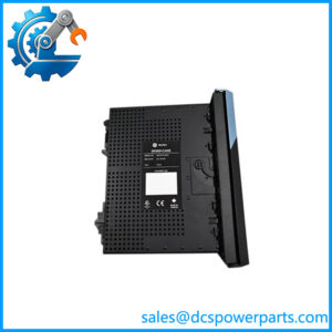
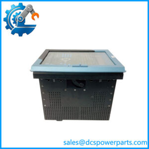
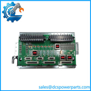
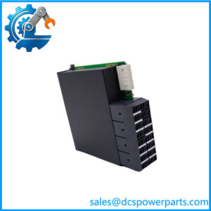
Grounding and field-device power distribution are easy to overlook during turbine control system maintenance, yet errors in either area can introduce signal noise or prevent field instruments from operating correctly. The GE IS400JGPAG1ACD is identified in equipment listings as a JGPA Ground Terminal Board for GE turbine control applications. The JGPA board family is documented in the Mark VIe control system hardware guides as a Ground and Power Board installed alongside the PCAA Core Analog module or TCAT terminal board. Its purpose is to provide shield-wire termination points and regulated power outputs for compatible field devices.
In the documented JGPA architecture, shield connections allow instrument cable shields to be bonded to the cabinet’s functional earth or connected to a designated grounding point. The board also provides 12 individually regulated 24 V DC field-device power outputs, each rated for 30 mA, with a nominal output tolerance of ±5%. These supplies are intended for compatible instrumentation, including applicable 4–20 mA field devices. The board receives its power feed from a compatible PCAA or TCAT assembly, so terminal wiring, connector placement, and the associated system configuration must be checked before installation.
For plant engineers and procurement teams, the GE IS400JGPAG1ACD should be evaluated as a specific grounding and power-distribution component, not as a general-purpose analog input/output card. Its role is to support the field wiring around the analog control subsystem rather than independently execute turbine control logic. During a replacement project, confirm the exact suffix, terminal arrangement, mounting method, and electrical interface against the installed board and applicable drawings. Where the board is used in a legacy turbine control cabinet, verifying shield-ground continuity and the available field-device supply voltage after installation is a practical part of commissioning. The GE IS400JGPAG1ACD should be purchased with a clearly stated condition and a documented inspection scope; a matching part number alone does not prove electrical performance.
Product Introduction (Non-Templated)
A missing shield-ground connection or unavailable transmitter supply can disrupt analog instrumentation even when the main controller remains operational. The GE IS400JGPAG1ACD is identified as a JGPA ground terminal board used in GE turbine control hardware.
The documented JGPA architecture provides 24 shield-ground terminals and 12 regulated 24 V DC outputs rated at 30 mA each. For a Mark VIe system upgrade or legacy replacement, verify the exact assembly revision and mating hardware before reconnecting field wiring.
Key Technical Specifications
| Parameter | Value |
|---|---|
| Product Model | IS400JGPAG1ACD |
| Manufacturer | General Electric (GE) |
| Product Type | Ground Terminal Board / JGPA Ground and Power Board family |
| Control System Family | GE Mark VIe-related hardware; verify exact application for this suffix |
| Primary Function | Cable-shield grounding and field-device power distribution |
| Ground Terminals | 24 on TB1 and 24 on TB2 in the documented JGPA architecture |
| Field Power Outputs | 12 |
| Output Voltage | 24 V DC ±5% |
| Output Current Capability | 30 mA per output |
| Power Input | 28 V feed from a compatible PCAA or TCAT assembly |
| Terminal Conductor Range | 0.2–2.5 mm² for a single conductor, subject to terminal-specific requirements |
| Installation Method | Mounted adjacent to compatible analog terminal hardware |
| Operating Temperature | −30°C to +65°C for the documented JGPA architecture |
| Communication Protocol | No independent communication protocol established for the ground and power board |
| Protection Rating | Not verified for this exact part number |
| Condition | New surplus; verify stock condition and test records |
Specification note: The electrical characteristics above describe the documented JGPA board architecture. Confirm that the exact IS400JGPAG1ACD revision shares these specifications before using them as guaranteed acceptance criteria.
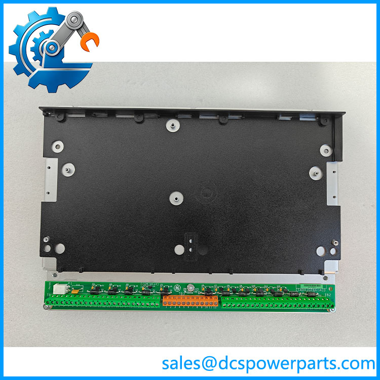
IS400JGPAG1ACD
Related Products
The following components are relevant to the JGPA ground and power board’s documented application. They serve different functions and should not be treated as interchangeable without engineering confirmation.
- IS200JGPAG1A — An earlier JGPA Ground and Power Board designation documented in GE Mark VIe hardware material. Compare the complete assembly and revision details before considering it for replacement.
- IS400TCASH1AGD — A related GE terminal-board designation appearing in component listings. Verify its exact terminal-board function and compatibility with the installed analog subsystem before procurement.
- PCAA Core Analog Module — The analog processing module associated with the documented JGPA architecture. It handles analog signal functions; JGPA supplies shield termination and field-device power rather than replacing the processing module.
- TCAT Terminal Board — Provides field signal termination for the compatible analog subsystem and can supply the JGPA power feed. Confirm the required board revision and cable arrangement.
- JGND Shield Ground Board — A related grounding component used with other GE Mark VIe terminal-board arrangements. Its grounding function overlaps with part of JGPA’s role, but it does not provide the same documented set of 12 regulated 24 V field-device power outputs.
- IS230PCAAH1B — A GE Core Analog I/O module designation identified in equipment listings. Its signal-processing role differs from JGPA’s grounding and power-distribution function; verify system generation and compatibility before considering it for the same project.
Frequently Asked Questions (FAQ)
1. What is the GE Ground Terminal Board used for?
The part is listed as a GE ground terminal board. The related JGPA architecture documented for GE Mark VIe hardware combines two functions:
- Terminating instrument cable shields for connection to functional earth or a designated grounding point.
- Providing 12 regulated 24 V DC outputs for compatible field devices.
It supports the analog instrumentation subsystem; it does not independently run the turbine control application. Verify the exact suffix against the installed board before applying the family-level specifications.
2. Is the compatible with GE Mark VIe PCAA and TCAT hardware?
The documented JGPA architecture is designed to operate alongside PCAA Core Analog modules and TCAT terminal boards. The JGPA receives its power feed through a compatible connection from PCAA or TCAT.
Before installation, check the connector assignment, wiring drawings, board revision, and required mounting arrangement. Do not assume that every board carrying a JGPA designation has an identical connector configuration.
3. Does the JGPA board provide 24 V DC power for transmitters?
Yes, the documented JGPA architecture provides 12 regulated 24 V DC outputs, each rated at 30 mA. This makes each output suitable for a compatible low-current field device when its electrical requirements fall within the specified limits.
Check the transmitter’s startup current and normal operating consumption before connecting it. A device requiring more than 30 mA must not be connected on the assumption that the board can supply the additional current. The documented design also provides individual output regulation and protection.
4. Can I hot-swap the GE while the turbine is running?
Do not assume that live replacement is permitted. The board’s role in grounding and field-device power distribution means that removing it could interrupt instrument supplies or alter shield-ground connections.
Use the approved maintenance procedure to determine whether the relevant equipment must be de-energized. Consider the effect on connected transmitters, process indications, and any active control functions before authorizing replacement.
5. How can I verify that a new-surplus is genuine and functional?
New surplus describes inventory status; it does not, by itself, establish authenticity or successful functional testing.
Request the following before purchase:
- Photographs showing the complete part number and revision markings.
- Available serial-number and inventory traceability records.
- Inspection results for terminals, connectors, corrosion, and physical damage.
- Test documentation stating what was measured and which tests were not performed.
For commissioning-critical equipment, confirm that the inspection procedure matches the board’s actual function. A visual inspection alone cannot demonstrate regulated output performance.
6. Will replacing this board erase my PLC or turbine control logic?
The JGPA board’s documented purpose is grounding and field-device power distribution, rather than storage or execution of the main turbine application logic. Replacing it would not ordinarily be expected to erase controller logic stored elsewhere.
However, the replacement may interrupt field-device power or affect connected signals. Record the wiring configuration, follow the approved isolation procedure, and verify transmitter power, grounding continuity, and signal quality after installation.
7. What should I check before ordering an replacement?
For an accurate procurement decision, confirm these points:
- Exact identity: Match the full number and revision markings.
- System compatibility: Verify the associated PCAA or TCAT hardware and the applicable system drawings.
- Electrical requirements: Confirm the incoming power connection, field-device current requirements, and grounding arrangement.
- Condition and warranty: Obtain written confirmation of the item’s condition, inspection scope, and warranty terms.
These checks help prevent ordering a board that looks correct but does not match the installed hardware or the site’s maintenance requirements.