Description
GE IS215VCMIH2CB
Product Introduction
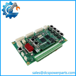
A Mark VI control rack can show an I/O communication fault even when the field I/O cards themselves are healthy. The GE IS215VCMIH2CB sits at the center of this communication path, functioning as the VME bus master and providing the interface between controller hardware, VME I/O boards, and the IONet system control network. In the H2 configuration, it provides three 10Base2 IONet ports and is associated with TMR Mark VI architectures.
The GE IS215VCMIH2CB uses a Texas Instruments TMS320C32 32-bit DSP and provides an RS-232C interface alongside its three IONet connections. It also handles rack-board identification and communication tasks within the Mark VI control architecture. For a legacy turbine installation, the IS215VCMIH2CB should be sourced by complete part number and revision, then checked against the existing IONet topology, controller configuration, firmware, and VME rack arrangement before installation.
Key Technical Specifications
| Parameter | Specification |
|---|---|
| Product Model | IS215VCMIH2CB |
| Manufacturer | General Electric |
| Product Series | Mark VI / Speedtronic |
| Functional Abbreviation | VCMI |
| Product Type | VME Bus Master Controller / Communication Board |
| Primary Function | Controller, I/O, and IONet communication |
| Form Factor | 6U VME |
| Board Width | Approx. 0.787 in. |
| Processor | Texas Instruments TMS320C32, 32-bit DSP |
| IONet Ports | 3 |
| IONet Physical Layer | 10Base2 Ethernet |
| IONet Connector | BNC |
| Serial Interface | 1 × RS-232C |
| VME Function | Bus master |
| System Architecture | TMR / H2 configuration |
| Dual-Port Memory | Approx. 32 KB |
| SRAM | Approx. 256K × 32 |
| Flash Memory | Reported as 512K × 8 for the VCMIH_B configuration |
| Monitored Supply Rails | +5 V, ±12 V, ±15 V, ±28 V |
| Rack Interface | VME backplane |
| Configuration | Mark VI engineering/configuration environment |
| Typical Application | Gas and steam turbine control |
| Manual Family | GEH-6421 series |
The most consistently documented characteristics are the 6U VME format, TMS320C32 processor, three 10Base2 IONet ports, RS-232C interface, and TMR-oriented H2 configuration. Some secondary references disagree on detailed frame-rate and power figures, so those values should be verified against the installed Mark VI system documentation rather than treated as universal specifications.
Application Scenarios & Pain Points
When the VCMI is unhealthy, the resulting symptoms can cross several layers of the Mark VI system: controller communication, I/O availability, rack identification, and IONet status. That makes a structured fault check much more useful than immediately swapping boards.
- Mark VI control racks: The VCMI serves as the communication interface between the controller and VME I/O boards while acting as the VME bus master.
- TMR turbine-control systems: The H2 configuration provides three IONet ports, supporting the separate communication paths used in TMR architectures.
- Remote I/O installations: IONet connects control and I/O racks, so cable condition, termination, and the remote VCMI must be considered when communication is lost.
- Legacy turbine maintenance: The board is relevant for maintaining existing Mark VI installations where a complete control-system migration is outside the outage scope.
Field note: If only one controller channel reports a VCMI fault, compare R/S/T channel behavior before declaring the board defective. A failed BNC connection, IONet cable, VME contact, or configuration issue can create a surprisingly similar symptom.
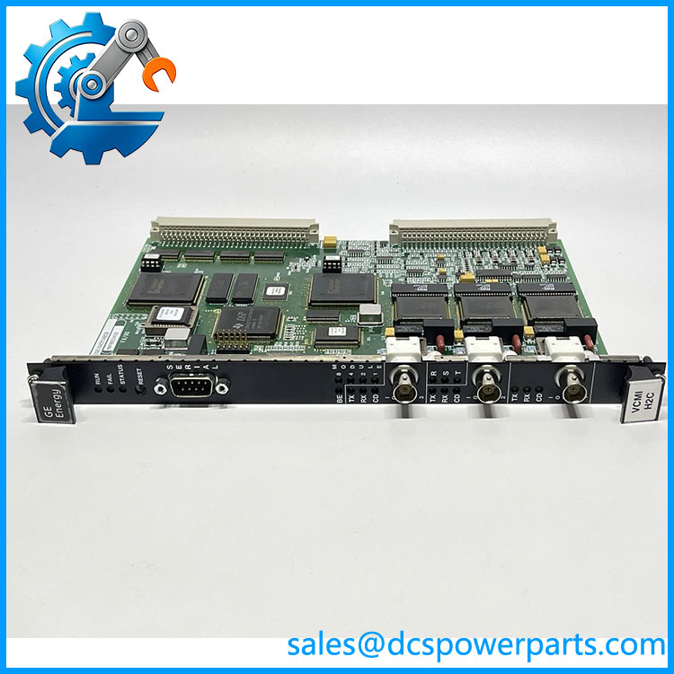
IS215VCMIH2CB
Related Products
- IS215VCMIH2C — Closely related VCMI H2 board; the complete suffix and revision must be compared before substitution.
- IS215VCMIH1B — VCMI H1 variant with a different IONet configuration; generally associated with simplex rather than the three-network H2 arrangement.
- IS215VCMIH2BC — Related H2 VCMI configuration with a different suffix; do not assume interchangeability with H2CB.
- IS215UCV-series controller boards — Mark VI controller hardware that works with the VCMI but performs a different processing function.
- IS215VPROH1B — Mark VI turbine protection hardware; complementary to the control architecture but not a VCMI replacement.
- Mark VI VME I/O boards — Process I/O hardware that communicates through the VME/VCMI architecture.
- Mark VI IONet infrastructure — BNC cabling and associated network components that should be inspected when troubleshooting VCMI communication faults.
Engineer’s Guide — Field Pitfalls to Avoid
1. Do not substitute the board by “VCMI H2” alone
The IS215VCMIH2CB is a specific hardware configuration. Other H2 boards may look almost identical while carrying different firmware, memory, or revision characteristics.
Avoidance tip: Record the full part number and revision markings from the original board before removal. Keep photographs of the front-panel connectors and configuration information.
2. Do not treat the three IONet ports as ordinary Ethernet
The H2 configuration uses three 10Base2 IONet connections as part of the Mark VI communication architecture. The ports have specific roles in the control-network arrangement.
Avoidance tip: Label the R, S, and T network paths before disconnecting the board. Check coaxial cable condition and termination before replacing hardware.
3. Check firmware and configuration before commissioning
The VCMI contains its own processor and memory resources and participates in real-time communication and rack identification. A replacement that powers up successfully is not necessarily ready for service.
Avoidance tip: Capture the original firmware/configuration information and compare it with the replacement before putting the board into a live control rack.
4. Inspect the VME backplane
The VCMI is a 6U VME board. Poor connector seating, contamination, or mechanical problems at the backplane can imitate a board-level failure.
Avoidance tip: Inspect the VME slot and connector condition during replacement. If a replacement produces exactly the same fault, investigate the rack before installing another board.
5. Check the monitored power rails
The VCMI monitors several internal supply rails, including +5 V and ±12/±15/±28 V supplies. Power abnormalities can therefore appear as communication or processor faults.
Avoidance tip: Measure rack supply conditions under operating load and review VCMI diagnostic information before condemning the communication board.
FAQ
What is the GE ?
The is a GE Mark VI VCMI VME Bus Master Controller. It provides communication between the controller and VME I/O boards and interfaces the rack with the IONet system control network.
What processor does the use?
The board uses a Texas Instruments TMS320C32 32-bit digital signal processor. This processor supports the board’s real-time bus and communication functions.
How many IONet ports are on the ?
The H2 configuration provides three 10Base2 IONet ports, normally using BNC connectors. This is one of the most important identification points when comparing the H1 and H2 VCMI variants.
Is used in TMR Mark VI systems?
Yes. The available technical documentation identifies the H2 VCMI configuration with TMR applications, where separate IONet paths support the redundant controller architecture.
Can replace IS215VCMIH1B?
It should not be assumed to be a direct replacement. The H1 and H2 configurations differ in IONet architecture; H1 is associated with a single IONet arrangement, while H2 provides three IONet ports for TMR configurations.
What should I check if the reports an IONet fault?
Start with the physical network: verify all three BNC connections, cable condition, termination, and the corresponding controller-channel status. Then check VME seating, rack power, firmware/configuration, and the remote I/O rack. This prevents a network fault from being mistaken for a failed VCMI.
What should be verified before purchasing a replacement?
Confirm the complete part number, hardware revision, three-port H2 configuration, processor/memory configuration, firmware, VME rack compatibility, and existing TMR architecture. For a turbine outage, a documented functional test is preferable to relying only on visual inspection or a basic power-on test.