Description
Key Technical Specifications
| Parameter | Value |
|---|---|
| Manufacturer | General Electric |
| Product Family | Mark VI |
| Model | |
| Functional Designation | TREG |
| Product Type | Turbine Emergency Trip Terminal Board |
| Board Variant | H1B |
| Primary Application | Turbine emergency trip / shutdown circuitry |
| Nominal Trip Solenoid Voltage | 125 VDC |
| DC Operating Range | Approximately 70–145 VDC |
| Emergency Trip Solenoids | 3 |
| Emergency Trip Relay Groups | 3 |
| Emergency Trip Relays | 9 |
| Economizing Relays | 3 |
| Terminal Blocks | 2 |
| Terminals | 24 per terminal block |
| Board Connectors | 3 jack connectors |
| Trip Relay Control | Redundant relay circuitry |
| Emergency Stop Input | Supported |
| Trip Interlock Inputs | Up to 7, depending on system configuration |
| Associated Mark VI Protection Module | VPRO |
| Associated Mark VIe Architecture | PPRO / SPRO |
| Configuration | Hardware jumpers plus system configuration |
| Typical Turbine Type | Gas or steam turbine |
The H1B designation is significant. GE documentation identifies H1B as the primary TREG version for 125 VDC applications. H2B is intended for 24 VDC systems, while H3B/H4B/H5B are special versions used in redundant TREG arrangements.
The TREG architecture uses three groups of emergency-trip relays, with each group associated with one trip solenoid. The board also incorporates economizing circuitry to reduce solenoid holding current after energization.
Product Introduction
GE
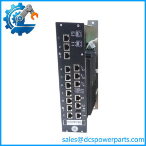
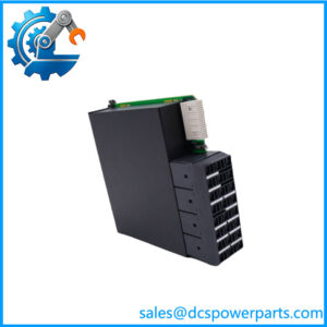
The GE is a Mark VI Turbine Emergency Trip (TREG) Terminal Board used in gas and steam turbine control systems. It provides the termination and relay interface for three emergency trip solenoids and works with the turbine protection architecture to remove the energy holding the turbine’s shutdown valves open when a trip condition occurs.
This is a safety-critical board. The H1B version is intended for 125 VDC trip circuits, and the TREG circuitry incorporates redundant relay paths, emergency-stop input handling, feedback monitoring, and economizing relays. It is not a generic Mark VI terminal board; the exact H-version must match the turbine’s installed trip-power architecture.
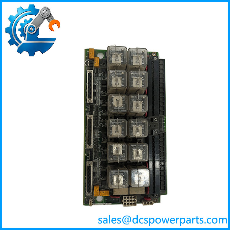
IS200TREGH1BDB
Application Scenarios & Field Pitfalls
Engineering Pain Point
A turbine can be running normally while the TREG circuit is carrying the burden of keeping the shutdown system energized. When that circuit develops a wiring, relay, fuse, or feedback problem, the control system may generate a trip-system alarm—or, under the wrong conditions, initiate a turbine trip. The TREG board therefore deserves much more scrutiny than an ordinary signal termination board.
Typical Applications
- Gas Turbine Power Generation — Emergency shutdown-valve control and turbine protection within a GE Mark VI control system.
- Steam Turbine Plants — Trip-solenoid control associated with steam admission/shutdown valves.
- Combined-Cycle Plants — Emergency trip circuitry for turbine trains integrated into the Mark VI protection architecture.
- Industrial Captive Power — Turbine protection and emergency shutdown circuits where continued operation depends on a properly supervised trip system.
Technical Pitfalls to Avoid
- Do not substitute H1B, H2B, H3B, H4B, or H5B casually.
This is the biggest procurement trap. H1B is the primary 125 VDC version, while H2B is intended for 24 VDC applications. H3B/H4B/H5B are associated with redundant TREG arrangements and deliberately maintain different control-power separation. - Verify the turbine’s trip-solenoid voltage before installation.
The TREG board is part of the actual shutdown circuit. A board variant selected solely because the base number “IS200TREGH1B” looks similar is not adequate engineering verification. - Check the TRPG relationship.
In the standard Mark VI arrangement, TREG provides the positive side of the DC supply to the trip solenoids, while the corresponding TRPG circuitry provides the negative side. Treat these boards as a circuit, not as isolated components. - Understand the Mark VI versus Mark VIe architecture.
In Mark VI systems, the TREG communicates with the VPRO protection module through molded cable connections. In Mark VIe systems, the corresponding interface is through the PPRO I/O pack and SPRO board. Confirm the actual turbine control architecture before ordering. - Do not ignore the economizing relays.
The TREG circuitry uses economizing relays to reduce holding current after the trip solenoids have been energized. A problem in this circuit can cause abnormal solenoid current or protection-system diagnostic indications. - Verify trip feedback, not just trip output.
The board participates in monitoring relay-driver and feedback conditions. A replacement should be tested for both command operation and diagnostic feedback. - Check the E-stop and interlock circuits independently.
External emergency-stop contacts and turbine protection interlocks can participate in the trip path. Do not assume a TREG replacement is correct merely because all terminal wires physically fit. - Do not megger connected electronic circuitry without an approved procedure.
The TREG contains relays, suppression components, and electronic circuitry. Insulation-resistance testing must be performed with sensitive electronics isolated as required by the plant’s maintenance procedure. - Treat the board as part of the turbine protection system.
Do not bench-test or bypass trip circuits casually. A wrong jumper, missing feedback signal, or incorrectly restored solenoid circuit can have consequences far beyond a simple I/O fault.
Related Products
- GE IS200TREGH1B — Base TREG H1B board designation associated with the same 125 VDC emergency-trip architecture. The complete suffix should still be matched when procuring a replacement.
- GE IS200TREGH1BDC — Related H1B TREG board revision. It belongs to the same emergency-trip board family, but the exact revision and compatibility should be verified against the installed turbine configuration before substitution.
- GE IS200TREGH1BEC — Another H1B-family TREG board variant. It may be relevant as a replacement only after checking the complete Mark VI hardware configuration and revision history.
- GE IS200TREGH2B — 24 VDC version of the TREG architecture. Functionally related, but not a direct substitute for an H1B board in a 125 VDC trip circuit. GE documentation specifically distinguishes H2B for 24 VDC applications.
- GE IS200TREGH3B — Special TREG version used in redundant TREG configurations. It changes the control-power arrangement and therefore requires application-specific verification.
- GE IS200TREGH4B — Special redundant-TREG variant. It is used with the corresponding redundant architecture to preserve separation of control-power paths.
- GE IS200TREGH5B — Another special redundant-TREG version. Its power-feed arrangement differs from the standard H1B configuration and should only be used where the system documentation calls for it.
- GE IS200TRPGH1B — Related turbine trip terminal board. In the standard architecture, TRPG provides the negative side of the trip-solenoid circuit while TREG handles the positive side.
- GE IS215VPROH1B — VPRO turbine protection hardware used with Mark VI TREG circuitry. The VPRO provides the protection-side control of the TREG board in Mark VI systems.
- GE IS215VPROH2B — Another VPRO hardware variant. Compatibility depends on the specific Mark VI protection architecture and should be checked against the turbine’s material list and hardware configuration.