Description
GE IS200TDBTH6ABC | TDBT Discrete I/O Terminal Board | Mark VIe Turbine Control
Key Technical Specifications
| Parameter | Specification |
|---|---|
| Manufacturer | General Electric |
| Model | IS200TDBTH6ABC |
| Functional Designation | TDBT |
| Product Type | Discrete Input/Output Terminal Board |
| System | GE Mark VIe |
| Contact Inputs | 24 isolated contact-input groups |
| Input Type | Dry/contact input with external wetting voltage |
| Wetting Voltage | 24 / 48 / 125 VDC nominal |
| 24 VDC Wetting Range | 16–32 VDC |
| 48 VDC Wetting Range | 32–64 VDC |
| 125 VDC Wetting Range | 100–145 VDC |
| Input Current | Approx. 2.5 mA for circuits 1–21; 10 mA for circuits 22–24 |
| Input Filter | Hardware filter, approximately 4 ms |
| Relay Outputs | 12 Form-C |
| Relay Load | Up to 3.15 A at 24 VDC or 120/240 VAC; lower ratings apply at higher DC voltage |
| Relay Feedback | Isolated contact-pair feedback |
| Relay Option Board | WROBH1A |
| I/O Pack Interface | JR1, JS1, JT1 |
| Mounting | DIN rail or flat panel |
| Board Dimensions | Approx. 17.8 × 33.0 cm |
| Operating Temperature | Published sources specify approximately -30°C to +65°C |
The TDBT design accepts externally supplied wetting voltage for its 24 isolated contact inputs. Three nominal voltage classes are documented: 24, 48, and 125 VDC. The input circuits include hardware filtering and noise suppression, while the relay section provides 12 Form-C outputs.
Product Introduction
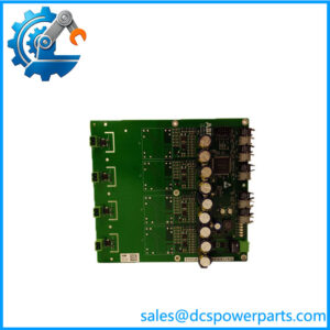
The is a TDBT discrete input/output terminal board used in the GE Mark VIe turbine control architecture. It provides the field termination and signal-conditioning interface for 24 isolated contact inputs and 12 Form-C relay outputs. The input section is designed for externally supplied 24, 48, or 125 VDC wetting voltage, making the board applicable to a range of turbine auxiliary and protection-related contact circuits.
The is not an independent PLC processor or conventional rack I/O card. It operates with the appropriate Mark VIe I/O pack architecture, with the TDBT providing the field-side interface while the I/O pack handles the controller communication. Three PDIO connection points support the applicable controller arrangement, including TMR configurations.
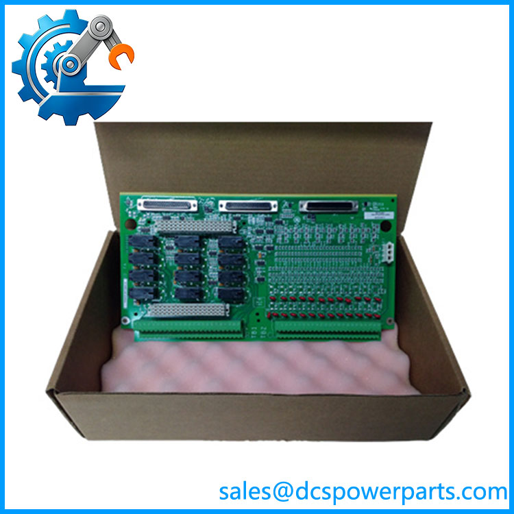
IS200TDBTH6ABC
Application Scenarios & Field Pitfalls — The Engineer’s Perspective
Engineering Pain Point
When troubleshooting a Mark VIe discrete I/O fault, it is easy to blame the terminal board when the actual problem is field wetting voltage, an I/O pack, relay circuitry, or controller-side communication. The should therefore be evaluated as one part of the complete TDBT/PDIO signal path.
Typical Applications
1. Turbine auxiliary contact monitoring
The 24 isolated contact inputs can monitor external dry contacts associated with turbine auxiliary equipment, interlocks, permissives, and status circuits.
2. Generator and turbine control systems
The board can provide contact input and relay output interfacing within GE Mark VIe control cabinets used for gas and steam turbine applications.
3. Relay-based control functions
The 12 Form-C relay outputs provide changeover contacts for external control circuits. Relay loading must remain within the voltage-dependent ratings of the contacts.
4. TMR turbine-control installations
The TDBT architecture can be used with multiple PDIO I/O packs for redundant controller arrangements. In a TMR configuration, each controller has its corresponding I/O communication path.
Technical Pitfalls
1. Do not confuse the board with the PDIO I/O pack.
The TDBT is the field termination/interface board. The PDIO is the active I/O pack that communicates with the Mark VIe controllers. Replacing one with the other is not a valid substitution.
2. Verify the wetting voltage.
The board supports 24, 48, and 125 VDC nominal wetting-voltage classes, but the actual input ranges differ. The external supply must match the field circuit design.
3. Check relay loading at the actual voltage.
The relay contact rating is not a single universal current value. Published data gives different maximum loads for 24 VDC, 48 VDC, 125 VDC, and 120/240 VAC. Treating the highest current figure as valid for every voltage is incorrect.
4. Do not assume TMR from the board number alone.
TDBT hardware can participate in redundant architectures, but the actual system configuration depends on the number and arrangement of PDIO I/O packs and controllers.
5. Inspect the WROBH1A option board when relay power distribution is involved.
The WROBH1A adds specific relay power-distribution functionality. Its jumpers and fuse arrangements should be checked when troubleshooting relay behavior.
6. Check the revision suffix.
The exact part number is , not simply IS200TDBTH6A. GE Mark VI/Mark VIe terminal boards exist in multiple hardware configurations, so the complete catalog number should be matched before replacement.
7. Be careful with Mark VI versus Mark VIe identification.
Public listings sometimes describe this board inconsistently. The TDBT documentation associates this architecture with Mark VIe and PDIO I/O packs. Do not substitute it into an older Mark VI installation merely because the board number looks similar.
Related Products
- GE IS200TDBTH6A — base TDBT terminal-board designation; verify exact suffix and system configuration before substitution.
- GE IS230TDBTH6A — Mark VIe packaged TDBT assembly associated with the IS200TDBTH6A board.
- GE IS200TDBTH2A — related TDBT discrete I/O terminal-board variant.
- GE IS200TDBTH4A — related TDBT terminal-board variant with different application configuration.
- GE IS200TDBTH6ACD — related TDBT revision/configuration; not automatically interchangeable with the ABC version.
- GE IS200WROBH1A — relay option board providing additional relay power-distribution functionality.
- GE PDIO I/O Pack — active Mark VIe I/O pack used with the TDBT architecture.
- GE IS200TRLYH1B — related relay terminal-board architecture.
- GE IS200STCIH2A — related discrete contact-input terminal-board family.
- GE IS200TDBSH2A — related TDBS discrete terminal-board family.
Procurement Note
For replacement, the critical information is not simply “TDBT terminal board.” Confirm the complete part number, revision, wetting-voltage class, PDIO configuration, relay requirements, and controller architecture.
For a used or surplus board, inspect the terminal blocks, relay contacts, connectors, PCB condition, corrosion, contamination, and evidence of field overvoltage. If the board is being supplied with a WROBH1A option board, verify that the option-board configuration matches the original installation.
Most importantly, do not accept listings that describe the as an embedded processor, generic analog board, servo board, or standalone controller. The technically defensible classification is GE Mark VIe TDBT Discrete Input/Output Terminal Board.