Description
GE IS200JPDBG1ABB AC Power Distribution Board
Product Introduction
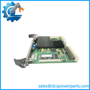
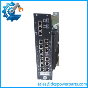
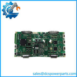
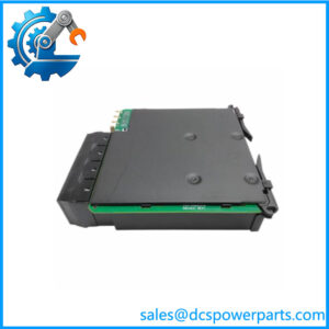
The GE IS200JPDBG1ABB is a JPDB AC Power Distribution Board used in GE Mark VI turbine control power-distribution equipment. The board forms part of the IS2020JPDB AC module and provides the switching, fusing, distribution, and monitoring functions required to route AC control power to downstream equipment. It is not a CPU, communication processor, or conventional PLC I/O card. The available technical records identify the board as part of the AC power-distribution architecture used within GE Speedtronic turbine-control cabinets.
The GE IS200JPDBG1ABB contains two AC distribution circuits. Available technical documentation describes each circuit as capable of handling up to 20 A at either 115 VAC or 230 VAC, with one fused branch and three fused/switched branch outputs. When a single AC source is used, the input circuits may need to be wired in parallel according to the applicable PDM configuration to prevent power-distribution alarms. Diagnostic signals are routed through the board interface to the associated PPDA electronics, including electronic identification and AC supply feedback.
The GE IS200JPDBG1ABB also incorporates field-replaceable circuit protection and local switching hardware. Technical records describe six toggle switches and eight fuses on the PCB, together with ribbon-cable connections used for monitoring and signal pass-through. Because these circuits can distribute cabinet AC power, replacement should be approached as an electrical power-distribution task rather than ordinary PCB substitution. The complete part number, associated IS2020JPDB configuration, AC source arrangement, fuse values, branch wiring, and revision should be checked before commissioning.
Technical Specifications
| Parameter | Specification |
|---|---|
| Product Model | IS200JPDBG1ABB |
| Manufacturer | General Electric |
| Functional Acronym | JPDB |
| Product Type | AC Power Distribution Board |
| Associated Assembly | IS2020JPDB AC Module |
| System | GE Mark VI / Mark VIe PDM architecture |
| AC Distribution Circuits | 2 |
| Circuit Capacity | Up to 20 A per circuit |
| Supported AC Voltage | 115 VAC or 230 VAC |
| Branch Arrangement | 1 fused + 3 fused/switched outputs per circuit |
| Input Configuration | Separate or parallel-connected sources according to PDM configuration |
| Circuit Protection | On-board fuses and switching |
| Monitoring | AC magnitude / fused-circuit status feedback |
| Diagnostic Interface | Ribbon-cable monitoring connections |
| Board Identification | Electronic ID through board interface |
| Local Switching | Six toggle switches reported |
| On-Board Fuses | Eight reported |
| Physical Size | Approximately 15.9 × 10.2 cm |
| Operating Temperature | -30 to +65°C reported in secondary records |
| Mounting | Cabinet-mounted PDM assembly |
| Communication | No standalone Ethernet/fieldbus function |
| Revision | G1 / ABB hardware revision |
| Lifecycle | Legacy GE Mark VI hardware |
Specification note: The 20 A, 115/230 VAC figures and branch-output arrangement come from secondary technical records for the JPDB assembly. They should be checked against the actual GE cabinet drawing when specifying a replacement, especially where the board is installed in a site-specific PDM configuration.
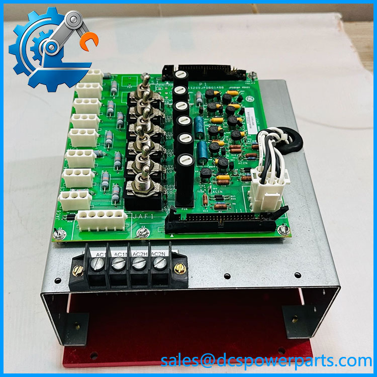
IS200JPDBG1ABB
Main Features and Engineering Considerations
1. AC Power Distribution
The GE IS200JPDBG1ABB is fundamentally a power-distribution component. Its purpose is to take the cabinet’s AC supply and divide it into protected branch circuits for the equipment connected to the PDM assembly. This makes it an infrastructure board within the Mark VI cabinet rather than a control processor.
2. Two Distribution Circuits
The JPDB architecture contains two AC distribution circuits. Each circuit is documented for up to 20 A at 115 or 230 VAC. The actual current available to a branch remains dependent on the installed fuse, cabinet wiring, upstream protection, and the specific PDM configuration.
3. Fused and Switched Branches
Each distribution circuit has one fused branch and three fused/switched branch outputs in the documented configuration. This arrangement allows individual downstream AC feeds to be protected and selectively switched rather than placing every load on one common branch.
4. Monitoring and Diagnostics
The board does more than simply distribute power. Its monitoring circuitry provides feedback associated with the fused AC circuits, while the board interface passes diagnostic information toward the associated PPDA electronics. Electronic identification is also used by the Mark VI architecture.
5. Ribbon-Cable Interfaces
Technical records identify two ribbon-cable connectors, positioned toward the short edges of the PCB, for monitoring and signal pass-through. These connections should be carefully documented before removal. A misplaced ribbon cable can produce apparently unrelated diagnostic faults elsewhere in the power-distribution system.
6. Physical Switching and Fusing
The board includes six toggle switches and eight fuses in the documented hardware arrangement. This provides local circuit protection and switching at the board level. Fuse condition should be checked during troubleshooting rather than immediately assuming a failed PCB.
7. Parallel Input Configuration
When a single AC source is used with both distribution circuits, technical records specify a parallel input arrangement in applicable configurations. This is particularly important because an incorrect input configuration can generate PDM alarms or abnormal power-distribution indications. Always follow the cabinet-specific wiring diagram rather than applying a generic jumper or wiring assumption.
Application Scenarios
- GE Mark VI turbine control cabinets
- GE Mark VIe-related power-distribution assemblies
- Gas turbine control systems
- Steam turbine control systems
- AC control-power distribution
- PDM cabinet power branches
- Turbine I/O and control-equipment power feeds
- Legacy Speedtronic maintenance
- GE turbine control cabinet refurbishment
- Replacement of failed JPDB assemblies
Engineer’s Guide: Field Pitfalls
Do not confuse JPDB with a processor board.
The distributes and monitors AC power. It does not execute turbine-control logic.
Verify the AC voltage before replacement.
The documented JPDB configuration supports 115 VAC and 230 VAC circuits. Confirm the actual cabinet source and wiring before installing or testing the board.
Check all fuses before condemning the PCB.
Eight fuses are reported on the board. A blown fuse may indicate a downstream load problem rather than a JPDB failure.
Document the toggle-switch positions.
The six local switches are part of the board’s distribution arrangement. Record their original state before removing the board.
Check ribbon-cable orientation.
The monitoring/pass-through ribbon cables should be photographed and labeled before removal. Connector reversal or displacement can affect PDM diagnostics.
Verify parallel-input wiring.
If the cabinet uses a single AC source for both distribution circuits, confirm the required parallel configuration from the applicable GE drawing. Do not improvise the input connection.
Do not substitute based on the “JPDB” name alone.
GE has multiple JPDB/JPD-family boards. Related boards such as JPDD, JPDF, JPDH, JPDM, and JPDV serve different power-distribution functions. The complete part number must be matched.
Inspect downstream loads after a fuse failure.
Replacing a blown fuse without identifying the cause can damage the replacement board or recreate the same fault.
Treat the board as an AC power component.
This is not a low-voltage signal PCB. Appropriate isolation, absence-of-voltage verification, and discharge procedures are required before maintenance.
Frequently Asked Questions
What is GE ?
It is a GE JPDB AC Power Distribution Board associated with the IS2020JPDB power-distribution assembly used in GE turbine-control systems.
What does JPDB stand for?
JPDB is the functional abbreviation associated with the AC Power Distribution Board in this GE Mark VI power-distribution architecture.
What voltage does distribute?
The documented JPDB configuration supports 115 VAC and 230 VAC distribution circuits, with each circuit rated up to 20 A in the referenced configuration.
How many AC distribution circuits are provided?
The documented assembly has two AC distribution circuits.
How many branch outputs are available?
Each circuit is described as having one fused output and three fused/switched outputs.
Is an Ethernet board?
No. It is an AC power-distribution board. The online listing that describes this part as an embedded Ethernet interface is inconsistent with the JPDB technical records and should not be used for product classification.
Is the same as IS200JPDBG2ABB?
No interchangeability should be assumed. Both belong to the JPDB family, but they are different part numbers and must be checked against the installed PDM architecture.
What is the relationship between and IS2020JPDB?
The is the PCB associated with the IS2020JPDB AC power-distribution module. Technical records specifically describe the as receiving its power through the JPDB board.
What should be checked before purchasing?
Verify the complete identifier, installed PDM assembly, AC source voltage, input configuration, fuse ratings, branch wiring, ribbon-cable connections, switch positions, and board revision.
Procurement Note
For a replacement , the useful verification package is a clear photograph of the complete PCB label plus the fuse/switch and connector areas. I would also request the installed configuration and the cabinet’s AC power-distribution drawing.
For refurbished inventory, “powers on” is not an adequate test. The meaningful checks are AC input path verification, fuse and switch continuity, branch-output testing, monitoring-feedback verification, ribbon-cable interface checks, and electronic board identification.
One final classification point: use AC Power Distribution Board / JPDB as the primary product description. The “Jumper Power Distribution Board” wording appears in some reseller records, while another listing incorrectly calls it an embedded Ethernet interface. The available JPDB functional records support the AC power-distribution classification.