Description
GE IS200EXAMG1BCB Exciter Attenuation Module
Product Introduction
The GE IS200EXAMG1BCB is an EXAM Exciter Attenuation Module used in GE EX2100 and EX2100e excitation-control systems. Its function is associated with field ground detection, where high-voltage signals from the excitation bridge must be reduced to an appropriate level before they are processed by the exciter ground detector. The EXAM works with the IS200EGDM Exciter Ground Detector Module rather than acting as the primary excitation controller. GE’s EXAM documentation describes the module as providing attenuation between the field bus and EGDM by sensing bridge voltage and scaling it to a usable level for the ground-detection circuitry.
The GE IS200EXAMG1BCB belongs to the IS200EXAMG1B hardware family. The complete suffix is important when ordering because GE’s board identification system uses the full catalog number to distinguish assembly, functional, and artwork revisions. GE documentation specifically states that all digits should be included when identifying a replacement board. The EXAM connects to the exciter power backplane, while the EGDM modules connect through the same backplane. In TMR configurations, multiple EGDM units can be arranged as C, M1, and M2 channels while the EXAM provides the attenuation interface.
For procurement, the GE IS200EXAMG1BCB should therefore be treated as a specialized excitation-system protection and monitoring component, not a general-purpose PLC I/O card. The most important compatibility checks are the EX2100 architecture, exact board revision, EPBP backplane arrangement, EGDM configuration, and jumper settings. Technical records identify JP1, JP2, and JP3 as configurable jumpers, including selection associated with PPT secondary-voltage conditions.
Technical Specifications
| Parameter | Specification |
|---|---|
| Product Model | IS200EXAMG1BCB |
| Manufacturer | General Electric (GE) |
| Functional Acronym | EXAM |
| Product Type | Exciter Attenuation Module |
| Excitation Platform | EX2100 / EX2100e |
| Primary Function | Exciter field-voltage attenuation for ground-detection circuitry |
| Associated Detector | IS200EGDM Exciter Ground Detector Module |
| Backplane | IS200EPBP Exciter Power Backplane |
| Installation Area | High-Voltage Interface / auxiliary cabinet |
| Field-Bus Connections | E1 / E2 stab-on connections |
| Auxiliary Connector | J1, 3-pin locking connector |
| Ground Connection | TB1 chassis/shield-ground terminal |
| Configuration | JP1, JP2, JP3 |
| Test Points | None identified in the EXAM functional description |
| Fuses | None identified in the EXAM functional description |
| Status LEDs | None identified in the EXAM functional description |
| System Architecture | Simplex and redundant/TMR applications depending on system configuration |
| Board Revision Family | G1B |
| Functional Documentation | GEI-100467 / GEI-100509 and related EX2100 documentation |
| Replacement Identification | Complete IS200EXAMG1BCB number should be matched |
Specification note: I have intentionally not populated a generic 24 VDC operating-voltage specification, Ethernet interface, CPU specification, or broad operating-temperature range. Those values appear in some reseller listings but are not supported by the EXAM functional documentation reviewed here. The EXAM is primarily an attenuation/interface circuit associated with high-voltage field-ground detection, so treating it like a powered digital controller would be misleading.
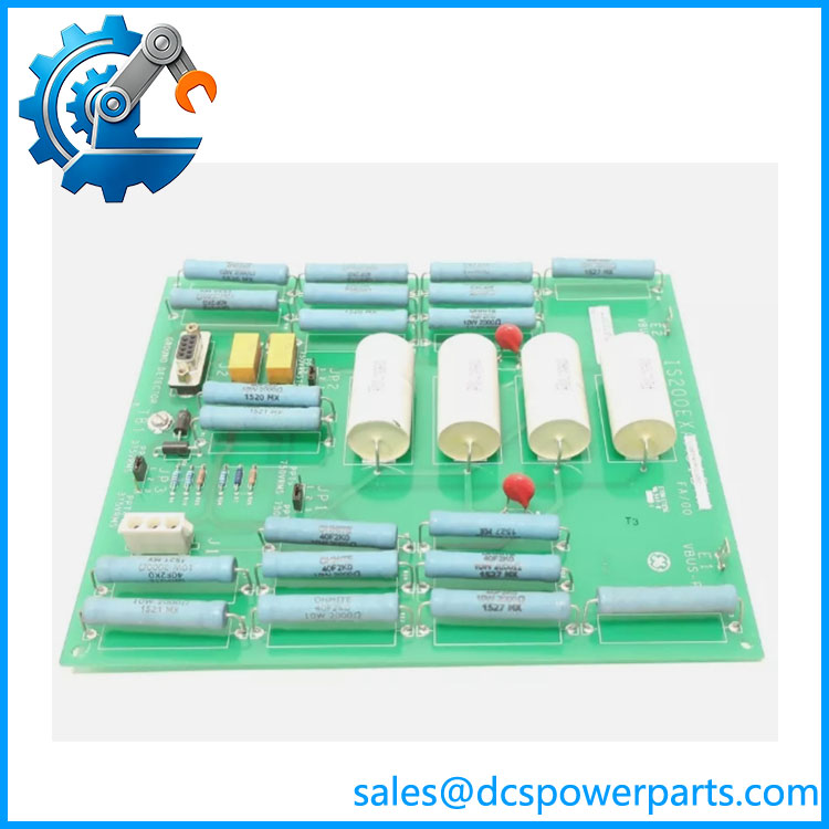
IS200EXAMG1BCB
Main Features and Engineering Considerations
1. Exciter Ground-Detection Function
The primary engineering purpose of the EXAM is attenuation. The module senses high voltage associated with the excitation bridge and scales that signal to a level suitable for the EGDM ground-detection circuitry. This makes the EXAM part of a protection/monitoring measurement chain rather than the main generator-voltage regulation processor.
2. Direct Relationship with EGDM
The EXAM and EGDM should be considered as a functional pair. The EGDM performs the ground-detection function using the signal conditioned by the EXAM. The two modules communicate through the IS200EPBP exciter power backplane.
3. Field-Bus Interface
The E1 and E2 stab-on connections provide the field-bus voltage connection to the attenuation circuitry. J1 is a three-pin locking connector associated with the field-flashing relay auxiliary contact, while TB1 provides the board shield/chassis-ground connection.
4. Jumper Configuration Matters
JP1, JP2, and JP3 are not cosmetic configuration links. The documented EXAM architecture uses jumper selection for the applicable signal/filter configuration. One technical description identifies two filter-capacitance arrangements corresponding to PPT secondary voltages below and above 750 V RMS. A replacement board should therefore be configured from the removed board’s documented settings and the excitation-system drawings rather than by copying a generic jumper arrangement.
5. No Generic PLC Interface
The should not be specified as a PLC analog-input module, Ethernet controller, or generic excitation CPU. Its job is narrowly tied to the EX2100 field-ground detection circuit. This distinction is important when preparing a spare-parts list because a visually similar IS200-series board does not imply functional interchangeability.
6. Revision Control
GE’s board-numbering documentation explains that different portions of the IS200 identifier describe the board family, functional revision, and artwork revision. The source documentation also notes that functional revision changes can have different compatibility implications. For an installed EX2100 system, the complete marking should be recorded before ordering.
Application Scenarios
- GE excitation-control systems
- GE EX2100e excitation systems
- Synchronous generator field-ground detection
- Excitation bridge voltage attenuation
- Generator excitation protection circuits
- High-voltage interface cabinets
- Auxiliary excitation-control cabinets
- Simplex configurations
- Redundant/TMR excitation architectures
- Legacy maintenance and spare-part replacement
Engineer’s Guide: Field Pitfalls
Do not mistake EXAM for the main excitation controller.
The EXAM is an attenuation/interface module associated with the EGDM ground detector. Listings that call an “Exciter Main Control Board” should not be used as the technical basis for interchange decisions.
Record the jumper positions before removal.
JP1, JP2, and JP3 form part of the board’s configuration. Photograph the original board and compare the settings with the applicable drawings before installing the replacement.
Verify the EPBP backplane.
The EXAM and EGDM modules use the IS200EPBP exciter power backplane. A replacement board should be evaluated together with the installed backplane and detector arrangement, not as an isolated PCB.
Treat the field-bus connections as high-energy circuitry.
The EXAM senses excitation-bridge voltage. Lockout, discharge, and verification procedures must be completed before physical work. Do not treat the board as a low-voltage control card simply because it is an IS200 printed circuit board.
Verify the exact board suffix.
The G1BCB identifier should be recorded exactly. GE’s own ordering guidance emphasizes complete part-number identification, including all revision characters.
Check simplex versus redundant architecture.
The number and arrangement of EGDM units can change with the system architecture. In TMR systems, the detector arrangement can include C, M1, and M2 modules. The replacement decision should therefore include the system drawings and existing EGDM configuration.
Frequently Asked Questions
What is GE ?
It is a GE Exciter Attenuation Module (EXAM) used as part of the excitation-system field-ground detection circuit.
What does EXAM stand for?
EXAM refers to Exciter Attenuation Module in the GE excitation-control documentation.
What does do?
It attenuates high-voltage excitation/field-bus signals to levels suitable for the associated EGDM exciter ground detector.
What module works with ?
The EXAM works with the IS200EGDM Exciter Ground Detector Module. Both are connected through the IS200EPBP exciter power backplane.
Is a PLC I/O module?
No. It is a specialized excitation-system attenuation/interface module.
Does have Ethernet?
No Ethernet interface is identified in the EXAM functional documentation reviewed for this part. It is a board-level excitation interface connected through the exciter power backplane.
How many EXAM boards are required?
The documented EXAM arrangement can use one EXAM for simplex and TMR configurations, while certain Alterrex/redundant applications can use two EXAM boards. The installed system architecture must be checked before determining the required quantity.
What should be checked before purchasing a replacement?
Verify the complete part number, board revision, system type, IS200EPBP backplane, IS200EGDM configuration, JP1/JP2/JP3 settings, and field-bus wiring.
Procurement Note
For a replacement , I would request a clear photograph of the board label plus the installed EGDM and EPBP identifiers. The most useful pre-shipment checks are exact part-number verification, jumper-position documentation, connector inspection, PCB condition, and functional testing of the attenuation/ground-detection path. Do not approve a substitute based only on the “EXAM” acronym; the complete GE board number and the excitation-system configuration determine whether the replacement is appropriate.