Description
Product Overview
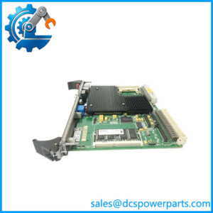
When a PLC must exchange discrete I/O data with a CNC controller or another device on a Fanuc I/O Link, the communication interface must match the link architecture and configured master/slave roles. The GE Fanuc IC697BEM721 provides this connection for Series 90-70 PLC systems. It supports serial data exchange over the Fanuc I/O Link, allowing the PLC application to monitor input states, update output states, and coordinate supported equipment without treating the link as a standard Ethernet network.
The GE Fanuc IC697BEM721 can be configured as either a master or a slave, depending on the system design. In master mode, it can exchange data with up to 16 slave devices; the manual describes a maximum distance of 10 meters (33 feet) between individual devices on a standard link, with compatible fiber-optic equipment available for longer distances. Before replacing the module, verify the configured operating mode, connected device types, cable arrangement, PLC program blocks, and software support. These details are especially important when maintaining legacy CNC and machine-control installations.
Key Technical Specifications
| Parameter | Specification |
|---|---|
| Product Model | IC697BEM721 |
| Manufacturer | GE Fanuc Automation |
| PLC Platform | Series 90-70 |
| Module Type | Serial I/O Link Interface |
| Communication System | Fanuc I/O Link |
| Operating Mode | Master or slave |
| Serial Interface | RS-422/RS-485 |
| Maximum Transmission Rate | 1.5 Mbps |
| Master Link Capacity | Up to 16 slave devices |
| Standard Link Distance | Up to 10 m (33 ft) between adjacent devices |
| Extended Distance | Up to 100 m (330 ft) with compatible fiber-optic adapters and cabling |
| PLC Rack Occupancy | One module slot |
| Installation Restriction | Cannot occupy rack 0, slot 1, which is reserved for the CPU |
| Maximum Modules per PLC | Up to four I/O Link Interface Modules |
| Status Indicators | Module OK, Link Active, Link Cfg |
| Reset | Front-panel I/O Link reset pushbutton |
| Power Supply | 5 VDC backplane supply; verify the rack power budget against the applicable manual |
| Operating Temperature | Confirm the specified range in the installation manual for the applicable revision |
| Protection Rating | No separate IP rating verified |
Major Features and Advantages
Master and slave operating modes
The IC697BEM721 can operate as either an I/O Link master or slave. In master mode, it manages data exchange with connected slave devices. In slave mode, it exchanges data with the master according to the configured I/O Link arrangement. The correct mode must be established in the PLC application rather than inferred from wiring alone.
CNC and machine-control connectivity
The module connects compatible Series 90-70 PLC systems to Fanuc I/O Link equipment, including supported Power Mate CNC devices. This can support coordinated machine operation where discrete input and output information must pass between the PLC and CNC control system.
High-speed serial data exchange
With a documented transmission rate of up to 1.5 Mbps, the module supports rapid I/O data exchange within the specified link architecture. Actual application performance depends on link configuration, the number of connected devices, and the PLC program.
Configurable multi-device link
A master can communicate with up to 16 slave devices. The PLC program must define the applicable device count, data length, I/O addresses, and link-control logic. These settings should be reviewed when changing hardware or rebuilding a legacy system.
Diagnostic LEDs and reset control
The three front-panel indicators provide information about module health, link activity, and configuration status. The reset pushbutton provides a local means of resetting the I/O Link interface according to the documented procedure. A lit status LED alone does not confirm correct data exchange with every connected device.
Fiber-optic distance extension
For installations where standard serial cable distance is insufficient, compatible optical adapters and fiber-optic cable can extend the link distance to the documented limit. Confirm the exact adapter, cable, and topology requirements before modifying an existing installation.
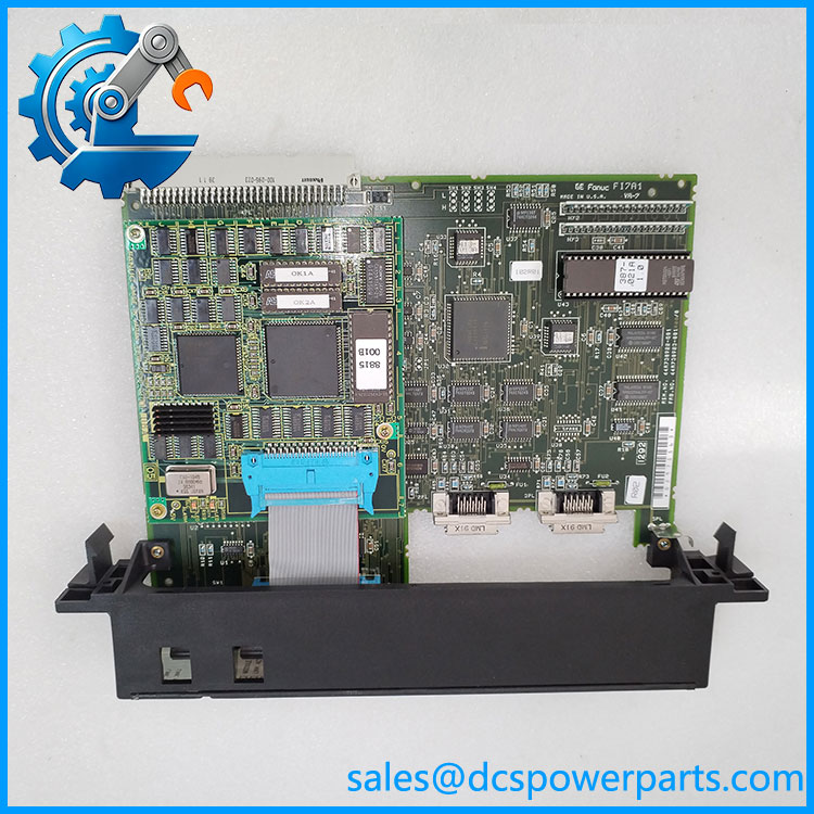
IC697BEM721
Application Scenarios and Common Pain Points
- PLC-to-CNC communication: Connects the Series 90-70 PLC with supported Fanuc CNC or Power Mate equipment over the I/O Link.
- Machine-tool control: Exchanges discrete I/O information used in machine sequencing and coordination.
- Legacy production equipment: Supports maintenance of installed control systems that depend on the proprietary Fanuc I/O Link.
- Distributed I/O communication: Connects supported master and slave devices through the documented serial link architecture.
Common troubleshooting points:
- Link inactive: Check cable continuity, connector seating, device power, master/slave configuration, and link termination requirements.
- Link configuration fault: Review the PLC program blocks, configured device count, I/O data lengths, and addressing.
- Intermittent data exchange: Inspect cable routing, electrical noise exposure, connector condition, and the distance between devices.
- CNC device not responding: Confirm that the connected device supports the same I/O Link configuration and that its assigned role matches the PLC setup.
- Replacement does not restore operation: Compare the hardware revision, application configuration, connected-device setup, and software support before concluding that the replacement is defective.
Related Products
These models are associated with the broader GE Fanuc Series 90-70 control platform or related communication functions. They serve different roles and should not be treated as direct substitutes without engineering verification.
| Model | Product type / distinction |
|---|---|
| IC697BEM731 | Genius I/O Bus Controller |
| IC697BEM733 | Genius Remote I/O Scanner |
| IC697BEM713 | Bus Transmitter for Series 90-70 rack expansion |
| IC697BEM711 | Bus Receiver for Series 90-70 rack expansion |
| IC697BEM741 | Fieldbus Interface (FIP) controller |
| IC697BEM744 | FIP Bus Controller |
| IC697CMM742 | Ethernet interface module |
| IC697CMM741 | Legacy Ethernet communication interface |
| IC697CPU780 | Series 90-70 CPU family component |
| IC697RCM711 | Redundancy Communications Module |
Engineer’s Guide: Three Checks Before Ordering
1. Identify the connected equipment and link role. Confirm whether the IC697BEM721 is configured as a master or slave and record the model numbers of all connected CNC or I/O Link devices.
2. Verify cabling and configuration. Check the RS-422/RS-485 cable arrangement, device spacing, any optical adapters, and the PLC program’s I/O Link configuration. Do not assume that a generic serial cable or Ethernet cable can replace the specified link wiring.
3. Request documented functional testing. Confirm the complete catalog number and revision, module condition, and test scope. For a critical machine, request evidence of successful link communication rather than relying solely on a visual inspection or power-on test.
Installation warning: Follow the Series 90-70 manual for rack power-down, module insertion, and commissioning procedures. Do not remove or install the module in a live rack unless the system documentation explicitly permits the operation.
Frequently Asked Questions
1. What is the GE Fanuc IC697BEM721 used for?
It is a serial I/O Link Interface Module for the Series 90-70 PLC family. It enables communication with compatible Fanuc I/O Link equipment, including supported CNC and Power Mate devices.
2. Can the operate as both a master and a slave?
Yes. The module supports both operating modes, but the intended role must be configured in the PLC application. The connected devices and I/O data mapping must also match the selected arrangement.
3. What is the maximum communication speed?
The published maximum transmission rate is 1.5 Mbps. This is the serial I/O Link rate, not an Ethernet speed. Actual data exchange depends on the complete link configuration.
4. How many slave devices can one control?
In master mode, the documented interface supports up to 16 slave devices. Confirm the applicable device types, data lengths, and addressing in the system manual before commissioning.
5. Can the be replaced with an Ethernet module?
No, not as a direct functional replacement. The uses the proprietary Fanuc I/O Link, while an Ethernet module uses a different communication architecture. Replacing it with Ethernet hardware would require a separate engineering assessment of the connected equipment and control program.
6. What should be checked when the Link Active LED is off?
Check module status, cable connections, power to connected devices, master/slave roles, and the configured link topology. Use the manual’s LED diagnostic table to distinguish a configuration issue from a physical communication fault.
7. What information should buyers confirm before purchasing?
Verify the full catalog number, revision, physical condition, master/slave application, connected device types, functional-test results, warranty terms, and lead time. For a production-critical machine, confirm that the supplier can demonstrate the communication function needed by the installed system.
Procurement recommendation: The is a specialized legacy serial interface. Prioritize exact model identification and a functional test using a compatible I/O Link setup. Connector similarity or a successful power-on test alone is not enough to establish suitability for the intended machine.