Description
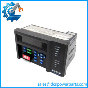
GE Multilin F650-N-F-B-F-2-G-0-HI-6E
Product Introduction
Protection engineers usually encounter the F650 where a feeder relay has to do more than simply issue a trip command. The GE Multilin F650-N-F-B-F-2-G-0-HI-6E belongs to GE’s 650 Family and combines electrical protection with bay-level control, metering, automation, event recording, and configurable logic. GE documentation specifically positions the F650 for distribution feeders and bus couplers, with applications extending to backup protection for buses, transformers, and power lines.
The exact suffix matters here. The F650 is a configurable platform, so two units carrying the F650 name can have different display, communications, I/O, power, and protocol arrangements. This -N-F-B-F-2-G-0-HI-6E should therefore be treated as a complete ordering code rather than interchangeable with every variant. For a legacy feeder replacement, verify the nameplate code, wiring arrangement, firmware, CT/VT configuration, communications board, and existing EnerVista settings before treating it as a drop-in replacement.
Key Technical Specifications
| Parameter | Specification |
|---|---|
| Manufacturer | GE Multilin |
| Model | -N-F-B-F-2-G-0-HI-6E |
| Product Family | GE Multilin 650 Family |
| Device Type | Feeder Protection and Bay Controller |
| Primary Application | Distribution feeder protection and control |
| Protection Functions | Phase, ground, neutral and sensitive-ground overcurrent; voltage, frequency, directional and power functions |
| Control Functions | Breaker control, breaker failure, autoreclose, synchronism check, programmable logic |
| Display | platform supports basic and graphical display configurations; exact display must be confirmed from the ordering code |
| Auxiliary Supply | HI: 110–250 VDC or 120–230 VAC nominal ranges documented for HI configurations |
| Communications | RS-232, RS-485 and Ethernet options depending on hardware configuration |
| Protocols | Modbus and other protocol options depending on configuration |
| Event Recording | Up to 479 events documented for the platform |
| Data Logging | Configurable data logger |
| Oscillography | High-resolution waveform capture |
| Installation | Panel-mounted digital protection relay |
| Software | EnerVista Setup |
| Condition | Confirm actual hardware/firmware condition before purchase |
The manual documents a wide protection set, including 50/51, 50N/51N, sensitive-ground, negative-sequence, voltage, frequency, directional power, breaker failure, autoreclose, and synchronism-check functions. It also documents event recording, oscillography, data logging, metering, and configurable logic.
For the HI power-supply designation, the documented ranges are 110–250 VDC with an 88–300 VDC operating range, or 120–230 VAC with a 96–250 VAC operating range. The manual also identifies redundant variants separately as HIR, so the presence of HI should not be interpreted as redundant auxiliary power.
Application Scenarios & Pain Points
A common field problem is not the protection algorithm itself; it is replacing a configured relay without preserving the original system assumptions. CT ratios, VT connections, breaker logic, trip supervision, communications mapping, and protection settings all have to agree. A relay can power up normally and still be unsuitable for service if one of these parameters is wrong.
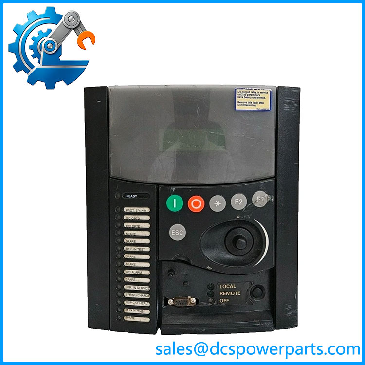
F650-N-F-B-F-2-G-0-HI-6E
Typical applications include:
- Medium-voltage distribution feeders: Phase and ground fault protection with breaker control and measurement.
- Substation bay control: Monitoring breaker status, issuing close/trip commands, and implementing programmable interlocking logic.
- Bus coupler protection: The platform is documented for feeder and bus-coupler applications, including configurable control schemes.
- Backup protection: Application as backup protection for buses, transformers, and power lines is specifically identified in GE’s documentation.
Field note: When replacing an installed , do not compare only the first four or five characters of the model number. The complete suffix defines hardware options. A unit that looks identical from the front can have a different communications or I/O arrangement at the rear.
Related Products
- GE Multilin -B-F-B-F-1-G-0-HI-6E — another configuration; useful as a comparison point, but its ordering code must be checked against the installed I/O and protection requirements.
- GE Multilin -N-F-G-F-2-G-1-HI-6E — another configured unit found in protection-system applications; configuration differences are significant.
- GE Multilin -N-C-G-F-2-G-1-HI-6E — alternative configuration used in feeder and substation protection applications.
- GE Multilin — base product family covering feeder protection, bay control, automation, and metering.
- GE Multilin CIO — remote CAN-based I/O expansion associated with installations requiring additional input/output capacity.
- GE Multilin TRCD–C-S-1 — -related accessory listed in GE’s catalog.
- GE Multilin ML2400-F-HI-HI-A2-A2-A6-G1 — network switch option commonly associated with GE protection-system architectures.
The documentation notes that additional I/O can be obtained through a CIO module, and the catalog lists the TRCD–C-S-1 and ML2400-F-HI-HI-A2-A2-A6-G1 among -related accessories.
Engineer’s Guide — Field Pitfalls to Avoid
1. Do not treat every as the same relay
The is an option-based platform. Display, communications, I/O, auxiliary supply, protocol, and environmental configurations can differ.
Avoidance: Compare the complete ordering string character by character with the existing relay before approving a replacement.
2. Verify the HI power supply
HI is associated with the high-range auxiliary supply configuration. The documented ranges are substantially different from the LO 24–48 VDC version.
Avoidance: Check the actual nameplate and control-power wiring before energizing a replacement.
3. Preserve the original protection settings
A replacement relay should not simply inherit a generic settings file. CT ratios, ground-current inputs, VT configuration, frequency settings, directional elements, breaker logic, and autoreclose parameters are application-specific.
Avoidance: Export and archive the existing configuration before removing the old unit whenever possible. Validate every protection group after loading the replacement.
4. Check firmware compatibility
documentation ties functionality and configuration to hardware and firmware revisions. The catalog also distinguishes newer ordering-code configurations from older hardware and firmware versions.
Avoidance: Record the firmware revision of both the removed and replacement relays. Do not assume that an older settings file can be transferred without verification.
5. Do not overlook communications hardware
RS-485, fiber-optic serial, and Ethernet capabilities are configuration-dependent. The manual identifies separate communications modules and specific fiber/Ethernet arrangements.
Avoidance: Photograph the rear communications section and compare connector type and module arrangement before procurement.
6. Treat breaker-control wiring as protection-critical
The relay may participate directly in trip, close, breaker-failure, and trip-circuit-supervision schemes.
Avoidance: Compare terminal wiring against the site schematic rather than relying on terminal position alone. GE specifically warns that communication-module insertion/removal should be performed with auxiliary power interrupted and rear terminals made potential-free.
FAQ
What is the GE -N-F-B-F-2-G-0-HI-6E used for?
It is a configured GE Multilin feeder protection and bay controller. Its application scope includes feeder protection, breaker control, electrical metering, automation, event recording, and programmable logic.
Is -N-F-B-F-2-G-0-HI-6E a PLC?
No. It is primarily a power-system protection relay and bay controller. It can provide programmable logic and control functions, but it should not be treated as a general-purpose PLC replacement.
What auxiliary power does the HI version use?
GE documentation specifies HI configurations for 110–250 VDC and 120–230 VAC auxiliary supply ranges, with wider stated operating ranges. Confirm the exact nameplate before applying control power.
Can another repl?
Not automatically. The platform uses configurable ordering codes. A replacement must match the required display, I/O, communications, power supply, protocol, and application-specific functions. The complete model code should be checked rather than relying on the family name alone.
Does the support Modbus and Ethernet?
The platform supports multiple communication interfaces and protocols, including RS-232/RS-485 and Ethernet options, with the exact implementation dependent on the installed communications hardware and configuration.
What should I verify when buying a replacement ?
At minimum, verify the complete part number, hardware revision, firmware revision, auxiliary-voltage code, communications hardware, I/O configuration, terminal arrangement, display type, and existing settings file. For a protection relay, those details matter more than cosmetic similarity.
Is new or refurbished?
The part number alone does not establish physical condition. New, unused, refurbished, and previously installed units can exist in the supply chain. For procurement, request the actual nameplate information, hardware/firmware revision, test evidence, and condition declaration for the specific unit being supplied.