Description
Product Overview
The GE Multilin F650-M-F-L-F-2-G-1-HI-S-6E is a configurable digital protection relay intended for medium-voltage distribution feeders and related substation applications. The F650 platform combines electrical protection, measurement, breaker control, and bay-level automation in a single device. Depending on the installed configuration and enabled settings, it can support phase and ground overcurrent protection, directional elements, voltage supervision, frequency protection, breaker-failure logic, synchrocheck, and automatic reclosing. These functions help protection engineers coordinate feeder trips and switching operations with the wider power-distribution scheme.
The F650 family also supports event recording, programmable inputs and outputs, configurable logic, and communication options for integration with substation monitoring and control systems. The actual capabilities of the GE Multilin F650-M-F-L-F-2-G-1-HI-S-6E depend on its ordered hardware, installed communication modules, firmware, and protection settings. In particular, do not infer the exact serial or fiber-optic interface, Ethernet capability, I/O count, or auxiliary supply solely from the F650 family name. Confirm these details against the relay’s identification label and the applicable ordering-code table in the manufacturer’s manual.
For replacement procurement, matching the full model number is essential. An F650 with a different communication board, digital I/O arrangement, or power-supply option may fit the same panel but still require wiring changes or fail to support the existing substation interface. Before changing the relay, preserve the original protection settings and logic, document CT/VT ratios and trip-circuit wiring, and confirm the configuration using the appropriate GE setup software and manual. Protection settings should be validated and tested before the feeder returns to service.
Product Introduction
The -M-F-L-F-2-G-1-HI-S-6E is part of GE Multilin’s digital feeder protection and bay control platform. It is intended for installations that require coordinated electrical protection, breaker operation, metering, and integration with substation automation systems.
When sourcing a replacement, confirm the complete ordering code, auxiliary supply, communication interfaces, I/O configuration, and firmware compatibility. Retain the existing settings and verify protection coordination before commissioning the replacement.
Key Technical Specifications
| Parameter | Details |
|---|---|
| Manufacturer | GE Multilin / GE Vernova |
| Model | -M-F-L-F-2-G-1-HI-S-6E |
| Product family | Multilin |
| Product type | Digital feeder protection relay / bay controller |
| Primary application | Distribution feeder protection and substation control |
| Protection functions | Family-level support includes overcurrent, directional, voltage, frequency, breaker failure, synchrocheck, and autoreclosing |
| Display | Depends on the ordered front-panel option |
| Communication interfaces | Depends on the ordered serial, fiber-optic, and Ethernet hardware |
| Digital I/O | Depends on the ordered I/O configuration |
| Auxiliary supply | Confirm the exact power-supply option from the nameplate |
| Protection settings | Configurable; must be matched to the protected circuit |
| Software | GE EnerVista 650 Setup; verify software and firmware compatibility |
| Mounting | Half-width, 19-inch rack format; 6U family design |
| Operating temperature | Verify the applicable model specification and installation conditions |
| Protection rating | Verify the applicable enclosure and installation requirements |
| Condition | Not specified |
| Lifecycle/support | Confirm current availability, repair support, and firmware access with GE Vernova |
Ordering-code caution: The full model number contains configuration fields, but I could not independently verify every character of -M-F-L-F-2-G-1-HI-S-6E against an authoritative configuration record. Do not use an unverified character-by-character interpretation to approve a replacement, specify wiring, or select the auxiliary supply.
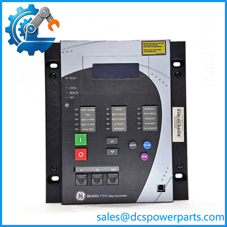
F650-M-F-L-F-2-G-1-HI-S-6E
Related Products
These products and resources are related to the platform, but are not necessarily direct substitutes.
- GE Multilin — The base feeder protection and bay control relay family.
- GE Multilin with alternate I/O configuration — Relevant when matching digital input, output, and trip-circuit supervision requirements.
- GE Multilin with alternate communications module — Relevant when matching serial, fiber-optic, or Ethernet connections.
- GE Multilin D400 — Substation automation platform that may be used in related monitoring and control architectures; it is not a replacement protection relay.
- CIO remote I/O module — An option associated with extending I/O capabilities in compatible system configurations.
- EnerVista 650 Setup — GE software used to configure and manage compatible relays.
- GE Multilin Instruction Manual, 1601-0800 — Manufacturer documentation for model configuration, installation, and operation.
Frequently Asked Questions
Q1. What is the GE Multilin -M-F-L-F-2-G-1-HI-S-6E used for?
It is an -family digital feeder protection and control relay. Its application includes electrical protection, measurement, breaker control, and substation bay automation. The precise functions depend on the ordered configuration and active settings.
Q2. Can I hot-swap this relay?
Do not assume hot-swap capability for the complete relay. Follow the manufacturer’s withdrawal and insertion procedures and the site’s electrical isolation requirements. Ensure that any required backup protection remains active while the relay is removed.
Q3. Does a replacement require firmware or settings changes?
Potentially. The replacement must be compatible with the existing firmware, configuration files, communication modules, and protection scheme. Back up the original settings and logic before removal. Verify the replacement’s configuration and perform the required protection and breaker-control tests before returning it to service.
Q4. Can I substitute another model?
Not without checking the complete ordering code. Variants may differ in auxiliary power, communication hardware, digital I/O, display, and other options. A relay that fits the same panel is not necessarily electrically or functionally equivalent.
Q5. Which communication protocols does this model support?
The family has configurable communication options, but the exact interfaces and protocol support depend on the installed hardware and firmware. Verify the relevant manual and the relay’s configuration before assuming support for a particular SCADA or substation protocol.
Q6. How do I verify the supplied unit’s authenticity and condition?
Request photographs of the full nameplate and rear terminals, the complete ordering code, serial number, and available test records. Establish whether the unit is new surplus, used, refurbished, or repaired. Ask for written warranty and return terms rather than relying on a generic “tested” description.
Q7. What information is needed before ordering a replacement?
At minimum, confirm the complete model code, auxiliary supply, I/O configuration, communication modules, firmware version, CT/VT settings, and existing protection configuration. If any of these differ, have a protection engineer review the proposed substitution before installation.