Description
Key Technical Specifications
| Parameter | Specification |
|---|---|
| Product Model | DS200TCPDG1BDC |
| Manufacturer | General Electric |
| Series | Mark V DS200 |
| Functional Acronym | TCPD |
| Product Type | Power Distribution Board |
| Functional Base Number | DS200TCPDG1B |
| Power Distribution | 125 VDC |
| External Power | 115/230 VAC |
| Software Configuration | None |
| Board Function | Mark V control-system power distribution |
| Toggle Switches | 8 |
| Fuse Positions | 36 |
| Fuse Status LEDs | 36 OK LEDs |
| Fault Indicators | 2 red LEDs |
| Signal Wire Terminals | 4 |
| 10-Pin Connector | 1 |
| Ground-Reference Jumper | BJS |
| PCB Coating | Normal coating |
| Host System | GE Speedtronic Mark V |
| Installation | Mark V control cabinet / core-specific |
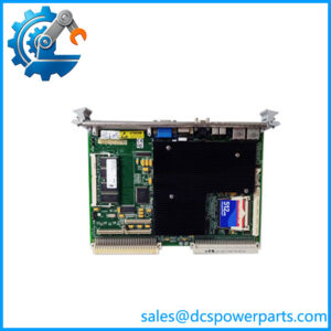
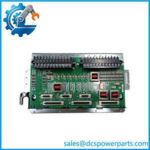
The TCPD board is documented as distributing 125 VDC to the Mark V Control Engine core, TCPS power-supply boards in the I/O cores, and the three TCEA emergency-overspeed boards in the protective cores. It also provides switching that can allow individual cores to be powered down.
The board hardware includes eight toggle switches, 36 fuses, four signal-wire terminals, 36 fuse-status LEDs, two red fault LEDs, and one 10-pin connector. The BJS jumper provides a ground-reference selection for applicable external-reference drive arrangements.
Product Introduction
The GE DS200TCPDG1BDC is a TCPD Power Distribution Board used in GE Mark V Speedtronic turbine control systems. Unlike Mark V analog, digital, or processor boards, the TCPD is concerned primarily with distributing and switching power to other parts of the control architecture. Its position in the system makes it important when multiple downstream boards lose power at the same time.
The complete part number should be retained during procurement. Public documentation identifies DS200TCPDG1B as the functional base designation and lists DS200TCPDG1BDC as a specific version. GE Mark V boards can have closely related suffixes such as BCC and BEC, so the full installed identification should be compared before substitution.
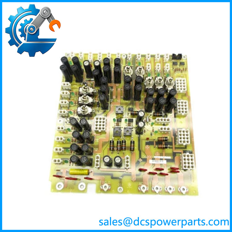
DS200TCPDG1BDC
Application Scenarios & Field Pitfalls — The Engineer’s Perspective
Engineering Pain Point
A TCPD fault can produce several apparently unrelated Mark V alarms because the board supplies multiple system sections. If the Control Engine core, I/O-core TCPS boards, or protective-core equipment simultaneously lose power, replacing each affected downstream board individually is the wrong diagnostic starting point. The common TCPD supply and distribution paths should be checked first.
Typical Applications
- Mark V Control Engine power distribution: Supplies the Control Engine core from the designated power-distribution architecture.
- I/O core power distribution: Feeds TCPS power-supply boards associated with Mark V I/O cores.
- Protective-core power distribution: Provides power to the three TCEA emergency-overspeed boards in the documented architecture.
- Core-level maintenance isolation: The board’s switches can be used to control power to individual Mark V cores during appropriate maintenance procedures.
Technical Pitfalls to Avoid
- Do not confuse TCPD with TCPS.
TCPD is the power-distribution board; TCPS is a separate Mark V DC power-supply board. They perform different functions and should not be substituted based on similar naming. - Check the incoming power before condemning the board.
A loss of several downstream boards can originate from the cabinet supply, upstream protection, wiring, or TCPD input rather than from an internal TCPD failure. - Check all 36 fuse-status indicators.
The board provides an individual OK LED for each fuse position. An extinguished indicator can identify a circuit requiring investigation, although the LED condition alone should not be treated as proof of the root cause. - Record switch positions before removal.
The eight toggle switches are part of the board’s power-distribution architecture. Their installed positions should be documented before maintenance. - Verify the BJS jumper.
The BJS jumper is associated with ground-reference isolation/connection for external-reference drive arrangements. Do not change its position without checking the applicable cabinet wiring and system documentation. - Do not assume all DS200TCPDG1B suffixes are interchangeable.
DS200TCPDG1BCC,DS200TCPDG1BDC, andDS200TCPDG1BECare separately listed part numbers. The complete board number should be matched before installation.
Related Products
- DS200TCPDG1B — Base TCPD Power Distribution Board designation. It establishes the functional family, but the complete suffix must be verified for replacement.
- DS200TCPDG1BCC — Another DS200TCPDG1B variant. Do not assume direct interchangeability with the
BDCversion without configuration verification. - DS200TCPDG1BEC — Another TCPD revision/configuration listed within the Mark V family; full compatibility should be confirmed before substitution.
- DS200TCPDG1A — Earlier TCPD Power Distribution Board designation. Hardware revision differences require verification before replacement.
- DS200TCPDG2B — Different TCPD power-distribution designation; not an automatic substitute for DS200TCPDG1BDC.
- DS200TCPSG1A — Mark V DC power-supply input board. It works in a different stage of the power architecture and should not be confused with TCPD.
- DS200TCPAG1A — Mark V Turbine Control Processor Board; processing function rather than power distribution.
- DS200TCEBG1BAA — Mark V Protective Termination Expander Board; handles a different protection-signal function.
- DS200TCEA-family boards — Mark V emergency-overspeed boards supplied within the broader protective architecture served by TCPD.
Procurement and Replacement Note
For a GE DS200TCPDG1BDC replacement, specify the complete part number rather than ordering a generic “TCPD board.” Record the board label, functional revision, cabinet/core location, fuse arrangement, switch positions, and BJS jumper position before removal.
The most important compatibility check is the power-distribution architecture of the installed Mark V cabinet. Confirm which Control Engine, I/O-core, TCPS, and protective-core circuits are actually connected to the board. The documented 125 VDC distribution role should also be checked against the cabinet drawings and installed power-supply arrangement before energization.
Do not use generic reseller figures such as “30 A per channel,” IP20, or a particular total power capacity as engineering limits unless they can be traced to the applicable GE documentation. Those values appear in secondary listings but are not sufficiently established for this exact configuration.
For troubleshooting, start with the common supply path: incoming power → TCPD protection/distribution → individual fuse/switch circuit → downstream TCPS/control/protection equipment. That sequence is more useful than immediately replacing a downstream Mark V board that happens to be reporting a loss of power.