Description
GE DS200TBQBG1ACB RST Analog Termination Board
Product Introduction
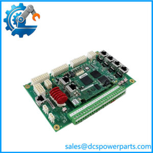
The GE DS200TBQBG1ACB is an RST Analog Termination Board used in the GE Mark V Speedtronic turbine control system. Its primary job is to provide the field termination and signal-routing interface for analog and related turbine-monitoring inputs. The board is not the main processor or an independent analog controller. Instead, it sits within the Mark V I/O architecture and passes field signals toward associated control and acquisition boards such as TCQA and TCQC. Exact signal assignments depend on the cabinet design and the installed Mark V configuration.
The GE DS200TBQBG1ACB has two terminal blocks, each containing 77 signal-wire terminals, giving the board 154 documented field-wire positions. It also carries 15 hardware jumpers, three 34-pin connectors, and three 16-pin connectors. The jumper groups have specific circuit functions: BJ1–BJ4 are used for pressure-transducer signal fan-out, BJ5–BJ7 provide burden-resistor configuration for pressure-transducer circuits, and BJ8–BJ15 are associated with analog-input configuration. This makes jumper verification a necessary part of replacement work rather than an optional commissioning check.
For procurement, the complete GE DS200TBQBG1ACB identifier should be matched. The A/C/B revision combination is significant, and another TBQB board should not be treated as a direct substitute simply because it carries the same functional acronym. Field wiring, connector population, jumper positions, R2/R3 core location, and the associated TCQA/TCQC boards should be checked against the turbine’s engineering documentation before installation.
Technical Specifications
| Parameter | Specification |
|---|---|
| Product Model | DS200TBQBG1ACB |
| Manufacturer | General Electric (GE) |
| Product Series | Mark V / DS200 Speedtronic |
| Functional Acronym | TBQB |
| Product Type | RST Analog Termination Board / Input Termination Module |
| Primary Function | Analog signal termination and routing |
| Typical System Location | Position 7 in R2/R3 cores |
| Associated Boards | TCQA, TCQC |
| Terminal Blocks | 2 |
| Terminals | 77 per terminal block |
| Total Documented Terminals | 154 |
| Hardware Jumpers | 15 |
| 34-Pin Connectors | 3 |
| 16-Pin Connectors | 3 |
| Functional Revision 1 | A |
| Functional Revision 2 | C |
| Artwork Revision | B |
| PCB Coating | Normal coating |
| Communication Protocol | No standalone Ethernet/fieldbus function established |
| Working Voltage | Application-dependent; verify Mark V cabinet documentation |
| Operating Temperature | Not reliably established for the bare board |
| Protection Rating | Not independently established |
| Operating Accuracy | Not applicable as a standalone measurement device |
The exact terminal, jumper, connector, and revision information is supported by the strongest exact-part records. Some reseller listings publish generic 24 VDC / 1 A figures or a 0–10 VDC input range, but those claims are not sufficiently controlled to use as universal specifications for this board.
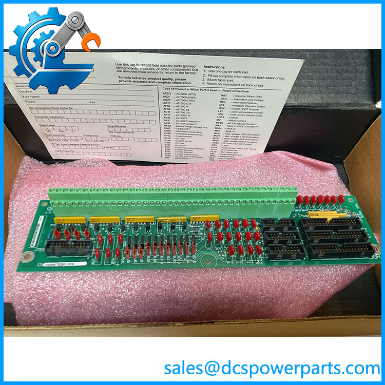
DS200TBQBG1ACB
Main Features and Engineering Considerations
RST Analog Termination Function
The DS200TBQBG1ACB is fundamentally an interface and termination board. Its purpose is to organize field signals before they reach the associated Mark V processing and acquisition circuitry. Treating it as a standalone analog input card can lead to incorrect troubleshooting because a bad signal may originate in the field transmitter, wiring, terminal connection, jumper configuration, TBQB, or downstream TCQA/TCQC hardware.
High-Density Field Wiring
Two terminal blocks with 77 terminals each provide a substantial connection interface. During replacement, terminal identification should be preserved before any wires are removed. Mark each wire with both the terminal-block designation and terminal number, such as TB1-66, rather than relying only on wire color or external cable tags.
Jumper-Selectable Signal Configuration
The 15 jumpers are a major engineering consideration. According to the exact-board technical record, BJ1–BJ4 are used to fan out pressure-transducer signals, BJ5–BJ7 install burden resistors for pressure-transducer circuits, and BJ8–BJ15 configure analog inputs. A replacement with incorrect jumper positions can therefore alter the signal interface even when the PCB itself is functioning correctly.
TCQA and TCQC Interfaces
The TBQB works with TCQA and TCQC boards within the Mark V architecture. Technical records identify connections involving TCQA analog circuitry and TCQC pulse-rate/detection circuitry. In R2/R3 configurations, the TBQB occupies a defined position within the control architecture, so the physical location and companion-board arrangement matter during troubleshooting.
Revision Control
The exact G1ACB suffix should be retained in procurement records. The board is documented with functional revisions A and C and artwork revision B. Do not assume that a visually similar DS200TBQB board has identical circuitry or jumper behavior.
Application Scenarios
- GE Mark V gas turbine control systems
- GE Mark V steam turbine control systems
- R2/R3 Mark V control cores
- Analog transmitter termination
- Pressure-transducer signal interfaces
- Turbine process-variable monitoring
- Vibration and condition-monitoring signal routing
- Pulse-rate and detection signal interfaces
- TCQA/TCQC field-signal termination
- Legacy Mark V control-panel refurbishment
Engineer’s Guide: Field Pitfalls
1. Do not confuse TBQB with TCQA.
TBQB is the termination/interface board. TCQA performs the associated analog I/O processing. They are separate components.
2. Record all 15 jumper positions.
This is especially important because the jumper groups serve different functions. Do not assume all jumpers are simply spare configuration links.
3. Verify R2/R3 location.
The TBQB is documented in position 7 within R2 and R3 cores. Confirm the actual cabinet drawing before installation.
4. Check connector population.
The board carries three 34-pin and three 16-pin connectors. Do not populate unused connectors simply because a replacement board provides the same physical interfaces.
5. Check pressure-transducer circuits carefully.
BJ1–BJ4 and BJ5–BJ7 have specific relationships to pressure-transducer signal splitting and burden-resistor configuration. Incorrect settings can change the electrical interface seen by the controller.
6. Do not copy specifications from another DS200 board.
TBQA, TBQB, TBQC, and other Mark V terminal boards can look similar while performing different interface functions.
7. Do not assume the board contains firmware.
The TBQB is a termination/interface assembly. Processing and control logic belong to the associated Mark V control electronics.
Frequently Asked Questions
What is GE ?
It is a GE Mark V TBQB RST Analog Termination Board, also identified as an Input Termination Module.
Where is installed?
Technical records place the TBQB in position 7 of the R2 and R3 cores of the Mark V system.
How many terminals does it have?
The exact board is documented with two terminal blocks containing 77 signal-wire terminals each, for 154 terminal positions.
How many jumpers are installed?
The board has 15 hardware jumpers, designated BJ1 through BJ15. Their functions include pressure-transducer signal fan-out, burden-resistor configuration, and analog-input configuration.
Which boards does TBQB interface with?
The TBQB is associated with TCQA and TCQC boards. In the documented architecture, the connections support analog, vibration, pulse-rate, and related turbine-monitoring signals.
Is an analog input module?
It is more accurately described as an analog/input termination board rather than a standalone analog-processing module. Its job is field signal termination and routing within the Mark V architecture.
Does it have Ethernet or Modbus?
No standalone Ethernet or Modbus function has been reliably established for this exact board. It is a Mark V termination/interface assembly.
What should be checked before purchasing a replacement?
Confirm the complete number, functional and artwork revisions, R2/R3 core location, terminal assignments, connector population, jumper positions, and associated TCQA/TCQC hardware.
Procurement Note
For a critical Mark V replacement, request clear photographs of the complete board identification, revision markings, both terminal blocks, all 15 jumper positions, and connector population. The exact suffix matters more than a generic “TBQB analog termination board” description.
For refurbished inventory, incoming inspection should include PCB condition, terminal integrity, connector condition, jumper verification, and continuity checks where appropriate. Functional acceptance should be performed against the actual Mark V cabinet configuration rather than against a generic TBQB specification.