Description
Key Technical Specifications
| Parameter | Specification |
|---|---|
| Product Model | DS200RTBAG3AHC |
| Manufacturer | General Electric |
| Series | Mark V / DS200 |
| Functional Acronym | RTBA |
| Product Type | Relay Terminal Board |
| Board Group | G3 |
| Functional Revision | A / H |
| Artwork Revision | C |
| Number of Relays | 10, K20–K29 |
| Relay Coil Voltage | 115 VAC |
| K20–K26 Contacts | 10 A DPDT |
| K27–K29 Contacts | 1 A 4PDT |
| Terminal Points | 52 |
| Control Power Connectors | CPH / CPN |
| Related Manual | GEI-100167 |
| PCB Coating | Normal coating |
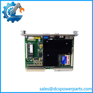
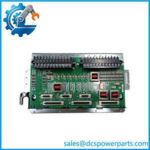
GE technical descriptions identify DS200RTBAG3AHC as an RTBA Relay Terminal Board for the Mark V control system. The board contains ten relays, designated K20 through K29, and 52 terminal points for I/O connections. The G3 configuration is specifically associated with 115 VAC relay coils.
The relay contact arrangement is important when checking a replacement: K20–K26 use 115 VAC coils with 10 A DPDT contacts, while K27–K29 use 115 VAC coils with 1 A 4PDT contacts. The board also uses CPH and CPN connectors for pluggable circuit control power.
Product Introduction
The GE DS200RTBAG3AHC is a Mark V RTBA Relay Terminal Board used to provide relay switching and field termination within GE turbine control and drive cabinet architectures. Its ten relays and 52 terminal points allow control signals to be routed through defined relay contacts rather than directly connecting external circuits to the controller electronics.
For maintenance engineers, the G3 configuration and relay arrangement are the critical identification points. This is not simply a generic relay interface board. The K20–K29 relay assignments, 115 VAC coil configuration, terminal layout, and board revision all affect interchangeability. A visually similar RTBA board should not be accepted as a substitute without confirming the complete part number and relay configuration.
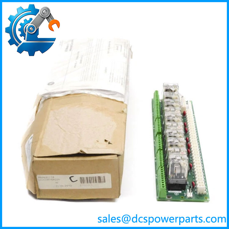
DS200RTBAG3AHC
Application Scenarios & Field Pitfalls
Engineering Pain Point
The DS200RTBAG3AHC is typically encountered in older Mark V installations where the control system may still be operating reliably but individual relay boards have become difficult to source.
The challenge is that relay boards with similar DS200RTBA naming can have different relay groups and electrical configurations. Installing the wrong variant can create a wiring or contact-rating mismatch even when the PCB appears physically compatible.
Typical Applications
- Gas turbine control systems — Relay interface and field termination for turbine control circuits.
- Steam turbine systems — Switching of control and auxiliary circuits within Mark V cabinets.
- Industrial drive cabinets — Relay-based interface functions associated with GE control equipment.
- Power-generation excitation/control equipment — Where the Mark V architecture uses RTBA relay termination for external control circuits.
The board is described as an optional cabinet-mounted relay terminal assembly, with relay outputs driven either directly from pilot relays or remotely by the user depending on the system configuration.
Technical Pitfalls to Avoid
1. Do not substitute by board family alone.
The parent DS200RTBAG3A identifies the base RTBA board, while DS200RTBAG3AHC includes functional and artwork revisions. The complete suffix should be matched during procurement.
2. Check the G3 relay configuration.
The G3 designation matters. K20–K26 and K27–K29 do not have the same contact arrangement or current rating. A replacement from another RTBA group may therefore have different electrical behavior.
3. Treat the board as potentially hazardous when energized.
The relay circuits include 115 VAC components, and technical descriptions specifically warn that hazardous energy can remain present on the board and associated drive equipment. Power isolation and the plant’s approved electrical safety procedure should be completed before handling the board.
Related Products
- DS200RTBAG3A — Base RTBA relay terminal board designation associated with the DS200RTBAG3AHC; verify revision and physical configuration before treating it as interchangeable.
- DS200RTBAG1A — Another RTBA board variant; relay configuration must be checked against the installed G3 board.
- DS200RTBAG2A — Related RTBA relay terminal configuration; not automatically equivalent to the G3 version.
- DS200RTBAG3 — Same RTBA G3 family designation, useful when tracing legacy documentation and board revisions.
- DS200DTBAG1A — Related Mark V terminal-board family used for different field-interface functions.
- DS200TBQAG1A — Mark V terminal board with a different I/O role and terminal arrangement.
- DS200TBCAG1A — Mark V terminal board family; application and circuit function differ from the RTBA relay board.
- DS200STBAG1A — Another DS200-series terminal/interface board; should not be treated as a relay-board substitute.
Procurement Check
For a , the purchase specification should include the complete model number, G3 board group, A/H functional revisions, C artwork revision, 115 VAC coil configuration, and relay contact arrangement. The strongest available technical descriptions agree on its identity as a 10-relay Mark V RTBA board with 52 terminal points.
I would not accept a listing that merely says “DS200RTBA relay board.” For a running Mark V turbine, the G3 configuration and exact suffix are part of the electrical compatibility check, not just inventory labeling.