Description
Key Technical Specifications
| Parameter | Specification |
|---|---|
| Manufacturer | General Electric |
| Part Number | DS200IIBDG1A |
| Functional Acronym | IIBD |
| Functional Description | AC2000 IGBT Board / IGBT Gate Driver Board |
| Product Family | Mark V DS200 |
| Board Function | IGBT gate-drive and feedback interface |
| Gate Driver Circuits | 6 optically isolated circuits |
| Output-Phase Arrangement | Upper and lower IGBT gate circuits for each phase |
| Current Feedback | Isolated current-feedback circuitry |
| Voltage Feedback | Motor-terminal voltage isolation circuitry |
| Gate Protection | IGBT gate-drive protection circuitry |
| Status Indication | 9 red LEDs |
| Manual Jumper | J1, used for gate turn-on delay selection |
| PCB Coating | Normal coating |
| Functional Revision | A |
The IIBD architecture uses six optically isolated gate-driver circuits, corresponding to upper and lower IGBT devices across three output phases. The board also contains current-feedback, motor-terminal-voltage isolation, and power-supply/gate-drive protection circuitry.
GE board documentation reproduced for this model identifies nine red status LEDs and a manually adjustable J1 jumper associated with gate turn-on delay.
Product Introduction
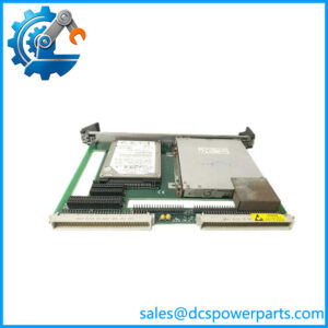
The GE DS200IIBDG1A is an IGBT gate-driver board used in GE Mark V/AC2000 drive hardware. Its job is at the boundary between low-voltage control electronics and the high-power IGBT switching stage: isolated gate-drive circuits command the semiconductor devices while feedback circuits provide information on current, terminal voltage, and fault conditions.
This is a drive power-electronics board, not a conventional PLC I/O card. That distinction matters during troubleshooting because a board failure can appear as an inverter, gate-drive, current-feedback, or power-stage fault rather than as a simple controller communication problem.
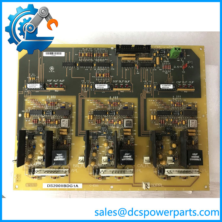
DS200IIBDG1A
Application Scenarios & Field Pitfalls — Engineer’s Perspective
Engineering Pain Point
The difficult part of replacing an IIBDG1A is preserving the relationship between the driver board, IGBT power devices, feedback circuits, and the specific GE drive cabinet. A board that physically fits the DS200 cabinet is not automatically electrically equivalent.
Typical Applications
- GE AC2000 drive systems — IGBT switching control and feedback.
- GE Mark V turbine-related drive cabinets — interface between control electronics and IGBT power stages.
- Industrial AC drive assemblies — isolated firing and monitoring of IGBT devices.
- Legacy turbine control maintenance — replacement of failed IGBT driver hardware while retaining the existing drive architecture.
Technical Pitfalls to Avoid
- Do not mistake DS200IIBDG1A for a discrete-input board.
Some current web pages incorrectly describe this part as a 32-channel, 24 VDC digital-input module. That description conflicts with the documented IIBD/IGBT board identity and should not be used for procurement. - Check the exact functional revision.
DS200IIBDG1A contains the A-rated functional revision. Other IIBD variants, including DS200IIBDG1AAA, DS200IIBDG1ACA, and DS200IIBDG1ADA, should not be assumed interchangeable without checking the drive documentation. - Record every connector before removal.
The board contains multiple connectors, and replacement requires reconnecting cables to their original positions. Misrouted gate-drive or feedback wiring can create a serious power-stage fault. - Do not change J1 casually.
The documented J1 jumper controls the board’s gate turn-on delay. Its original position should be recorded before replacement and compared with the applicable drive documentation. - Treat powered testing as high-energy work.
The board interfaces with an IGBT power stage and motor-terminal voltage. Testing around the energized board requires properly rated isolated instruments and established drive safety procedures.
Related Products
- GE DS200IIBDG1 — base IIBD / AC2000 IGBT board designation.
- GE DS200IIBDG1AAA — related IGBT driver-board configuration with additional functional/revision coding.
- GE DS200IIBDG1ACA — related AC2000 IGBT driver-board variant.
- GE DS200IIBDG1ADA — related GE Mark V AC2000 IGBT driver-board variant.
- GE DS200IAXSG1A — IGBT snubber board used with related GE drive power electronics.
- GE DS200GSNAG1A — GTO snubber board for other GE power-conversion configurations.
- GE DS200GSIAG1 — DC-bus/regenerative drive board family.
- GE Mark V DS200 — legacy GE turbine-control and drive-board platform.
- — drive architecture associated with the IIBD IGBT board.
Procurement Check
For DS200IIBDG1A, verify the following before approving a replacement:
Part number → DS200IIBDG1A
Functional acronym → IIBD
Function → IGBT gate driver/interface
Revision → A-rated functional revision
Drive → exact GE /Mark V cabinet and application
Connectors → compare every cable position
J1 → record original gate-turn-on-delay setting
Condition → verify board revision, coating, repair history, and test evidence
The most important procurement point is that is an IGBT power-electronics interface board, not a general-purpose PLC input/output module. The conflicting 24 VDC/PROFIBUS/digital-input specifications appearing on some current listings should be disregarded unless they can be traced to the actual GE documentation for the specific board.