Description
Product Introduction
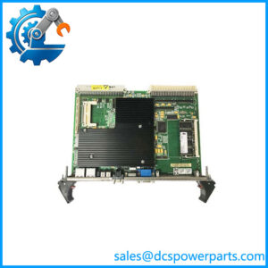
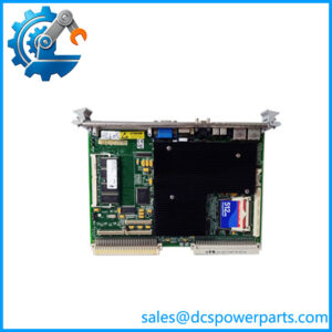
The GE DS200FGPAG1AHD is a Gate Pulse Amplifier Board used in GE’s LS2100 static-starter and LCI equipment. Its primary job is to provide the gate-drive interface for one phase of an SCR bridge while also monitoring SCR/cell status and handling the associated control-power conversion. The underlying DS200FGPAG1A board is documented with two gate-driver circuits and 30 test points, making it a specialized power-electronics interface rather than a conventional PLC or turbine CPU board.
The DS200FGPAG1AHD is a revision of the DS200FGPAG1A family. Available technical references list AHD alongside AMD, AKD, and AFC revisions. Importantly, the documentation explicitly identifies the board family as not backward compatible, so the complete hardware suffix should be treated as part of the replacement specification.
The board interfaces low-level control electronics with the high-power SCR bridge. Its fiber-optic interface provides electrical isolation between the control electronics and the high-power converter environment. The documented configuration contains 15 fiber-optic connectors—one transmitter and fourteen receivers—and gathers cell-status information from associated FHVA devices for transmission toward the LCI controller.
Key Technical Specifications
| Parameter | Specification |
|---|---|
| Manufacturer | General Electric |
| Model | DS200FGPAG1AHD |
| Base Model | DS200FGPAG1A |
| Series | LS2100 |
| Product Type | Gate Pulse Amplifier Board |
| Primary Function | SCR gate drive and status monitoring |
| Gate Driver Circuits | 2 |
| Test Points | 30 |
| Gate A Test Points | 9 |
| Gate B Test Points | 9 |
| Cell Status Test Points | 12 |
| Fiber-Optic Connectors | 15 |
| Fiber Transmitters | 1 |
| Fiber Receivers | 14 |
| Converter Configuration | 12-pulse |
| Converter Supply Voltage | 2080 or 3300 VAC |
| Power Input | 120 Vrms ±20%, 50/60 Hz reported |
| Maximum Power Consumption | Approx. 350 VA reported |
| Part-Specific Manual | GEI-100223 |
| Compatibility | Revision dependent |
The core board architecture is supported by available GE/LS2100 technical references. The 120 Vrms ±20% input and approximately 350 VA consumption are reported by secondary technical documentation and should be confirmed against the actual board documentation/nameplate for the specific installation.
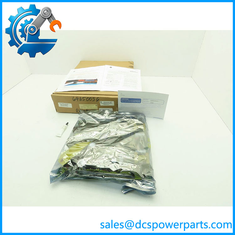
DS200FGPAG1AHD
Main Features and Advantages
SCR Gate Drive
The main function of the DS200FGPAG1AHD is to provide amplified gate-drive power for SCR devices in the LCI/static-starter power bridge. This makes it a critical interface between the control system and the high-power thyristor stage.
SCR Status Monitoring
The board receives cell-voltage/status information from associated FHVA modules and communicates this information through optical links toward the LCI controller. This allows the control system to monitor the condition of the SCR bridge rather than relying solely on the presence of a gate command.
Fiber-Optic Isolation
The 15 optical connectors provide a significant electrical-isolation boundary between control electronics and the high-voltage converter section. For LCI equipment, this is particularly important because the converter environment can produce substantial electrical noise and transient energy.
Integrated Power Conversion
The board includes switching-power circuitry that converts its incoming AC supply into the DC levels required for gate-drive and status-monitoring functions. This means the board should be evaluated as both a signal interface and a power-electronics assembly.
Field Diagnostics
The board provides 30 test points, divided among Gate A, Gate B, and cell-status monitoring. These points are useful when troubleshooting missing gate pulses, incorrect bridge status, or power-supply problems.
Application Scenarios
The DS200FGPAG1AHD is primarily relevant to:
- GE LS2100 Load Commutated Inverter (LCI) systems
- Gas-turbine static starter systems
- Large synchronous-motor starting systems
- Power-generation auxiliary starting equipment
- Legacy GE turbine-control installations using LS2100 hardware
- Maintenance and refurbishment of existing GE Mark-series equipment
It should not be described simply as a “Mark V CPU.” The board is a power-converter gate interface, and its function is substantially different from GE turbine controller and I/O boards.
Engineer’s Guide: Field Pitfalls to Avoid
⚠️ Do not ignore the AHD suffix.
The base designation DS200FGPAG1A has multiple revisions, including AHD, AMD, AKD, and AFC. Available documentation explicitly states that the board family is not backward compatible.
For procurement, specify:
GE DS200FGPAG1AHD
rather than simply “DS200FGPAG1A.”
⚠️ Do not confuse it with a controller board.
This is a Gate Pulse Amplifier Board, not a general-purpose processor or PLC CPU.
⚠️ Inspect the fiber-optic interface carefully.
Dirty connectors, damaged fibers, excessive bending, or incorrect fiber routing can produce communication and SCR-status problems that may initially appear to be board failures.
⚠️ Verify the converter voltage configuration.
The documented LS2100 application includes 2080 or 3300 VAC twelve-pulse converter configurations. The exact system configuration must be verified before replacement.
⚠️ Do not approve a refurbished board based only on a visual inspection.
A meaningful test should include the onboard power rails, gate-drive outputs, optical transmit/receive paths, SCR-status feedback, and relevant test points.
Frequently Asked Questions
What is GE ?
It is a Gate Pulse Amplifier Board in the GE DS200FGPAG1A family, used with LCI/static-starter equipment.
What does the board do?
It provides SCR gate-drive power, monitors SCR/cell status, and performs associated control-power conversion.
How many fiber-optic connections does it have?
The documented configuration has 15 fiber-optic connectors: one transmitter and fourteen receivers.
How many gate-driver circuits are provided?
The family is documented with two gate-driver circuits.
Is interchangeable with DS200FGPAG1AMD?
Do not assume so. The available documentation lists these as different revisions and states that the family is not backward compatible. Verify the exact system configuration before substitution.
What should I verify before purchasing?
- exact suffix
- base-board identification
- /LCI system compatibility
- Converter voltage configuration
- Fiber-optic connector arrangement
- Gate A/B circuitry
- Board power-supply condition
- SCR status feedback
- Hardware revision
- Functional test results
For a refurbished unit, I would specifically request evidence of gate-pulse output testing and fiber-optic communication testing, not just a powered-on inspection.