Description
Key Technical Specifications
| Parameter | Specification |
|---|---|
| Product Model | DS200DKLAG1ACA |
| Manufacturer | General Electric |
| Product Family | DS200 |
| Board Family | DS200DKLA |
| Functional Designation | DKLAG1A |
| Product Type | Display / Key / LED Board |
| Primary Function | Local display, keypad, and LED indication |
| User Interface | Keypad / display / LED indication |
| Hardware Revision | Verify from PCB marking |
| Artwork Revision | Verify from PCB marking |
| Communication Interface | Not reliably verified for this exact suffix |
| Supply Voltage | Not reliably verified for this exact suffix |
| Display Technology | Verify installed board |
| LED Quantity | Verify against physical board |
| Keypad Configuration | Verify against physical board |
| Operating Temperature | Verify against host-equipment documentation |
| Mounting | Cabinet/equipment-specific |
| Host Equipment | Verify from cabinet or drive documentation |
The broader DS200DKLAG1A designation is listed as a Display/Key/LED board in GE parts catalogs and automation-component records. A separate automation catalog also identifies DS200DKLAG1A as an LED Keypad Display.
Product Introduction
The GE DS200DKLAG1ACA is a DS200-series display and operator-interface board belonging to the DKLAG1A family. Its role is different from GE processor, power-supply, I/O, or signal-conditioning boards: it is associated with the local user interface, providing keypad/display and LED indication functions for the equipment in which it is installed.
This distinction matters during troubleshooting. A blank or malfunctioning local display does not automatically indicate a failure of the main controller. The interface board, its power path, mating connectors, display hardware, keypad circuitry, and host controller all need to be considered. The exact DS200DKLAG1ACA suffix should also be compared with the original PCB before substitution.
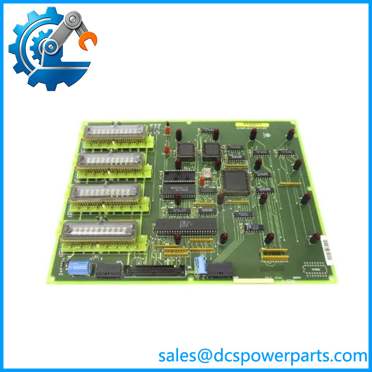
DS200DKLAG1ACA
Application Scenarios & Field Pitfalls — The Engineer’s Perspective
Engineering Pain Point
A failed display/keypad board can be mistaken for a controller or communication failure because the operator loses access to local status information at the same time. The first diagnostic question should be whether the underlying control equipment remains operational. If control functions continue while the local display or keys fail, the DKLAG1A interface path becomes a much more relevant suspect.
Typical Applications
- Local operator interface: Provides the display, keypad, and LED functions associated with compatible GE equipment.
- Status indication: LED indicators can provide local equipment-status information without relying entirely on an external workstation.
- Legacy GE maintenance: Used when maintaining equipment built around the DS200 board architecture.
- Interface-board replacement: Appropriate when the installed PCB identification specifically matches the DKLAG1A family and complete suffix.
Technical Pitfalls to Avoid
- Do not treat this as a general-purpose controller board.
The documented DKLAG1A function is display/key/LED related, not primary control processing. - Match the complete part number.
The broaderDS200DKLAG1Afamily contains related configurations, while the requested part is DS200DKLAG1ACA. Do not assume every DKLAG1A variant has identical connectors, firmware, or display hardware. - Do not assume a similar GE keypad board is interchangeable.
GE records also list DS200KLDAG1A, DS200KLDBG1A, and DS200KLDCG1A as separate Key/LED/Display families. Their similar descriptions do not establish electrical or mechanical interchangeability. - Check the host equipment before ordering.
The family appears across legacy GE equipment documentation, but the exact host application should be established from cabinet drawings, equipment model, and the original board label. - Inspect connectors before replacing the PCB.
A failed display can result from a loose connector, damaged ribbon cable, missing board supply, or upstream controller problem rather than a failed display board. - Do not publish unsupported electrical ratings.
I found reliable identification of the board family and function, but not a sufficiently authoritative source establishing exact supply voltage, display resolution, keypad matrix, connector pinout, or environmental limits for theG1ACAsuffix. Those values should be verified from the installed hardware documentation.
Related Products
- DS200DKLAG1A — Base Display/Key/LED board family. The closest documented family reference to DS200DKLAG1ACA.
- DS200KLDAG1A — Separate GE Key/LED/Display board family; similar functional description but not automatically interchangeable.
- DS200KLDBG1A — GE Key/LED/Display Board System designation; verify host application before considering substitution.
- DS200KLDCG1A — GE Key/LED/Display Board System / card family; separate hardware designation.
- DS215DKLAG1AZZ02A — DS215-series DKLAG1-related assembly with firmware designation; different board family and should not be treated as a direct DS200 replacement without documentation.
- DS200DMCAG1A — GE IOS/Main IOS Control board; this is a control-processing board rather than a local display/keypad board.
- DS200DMCBG1A — IOS/DUP processor board family; functionally different from the interface board.
- DS200DPCAG1A — Power Connect Card; different electrical role and not a substitute for the display/key board.
Procurement and Replacement Note
For GE DS200DKLAG1ACA, procurement should be based on the complete PCB identification rather than the generic description “GE keypad display.” Record the full part number, board revision/artwork markings, connector arrangement, and the GE equipment model in which the board is installed.
Pay particular attention to the difference between , DS200DKLAG1A, DS200KLDAG1A, DS200KLDBG1A, and DS200KLDCG1A. These are separate catalog designations even though several are described as display/key/LED boards.
For a field replacement, photograph the original board before removal and record all cable positions. If the replacement has a different connector population, display assembly, keypad arrangement, or revision marking, compatibility should be confirmed against the equipment documentation before energization.