Description
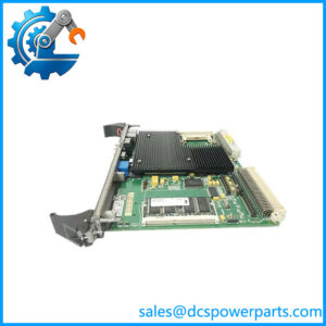
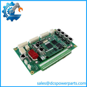
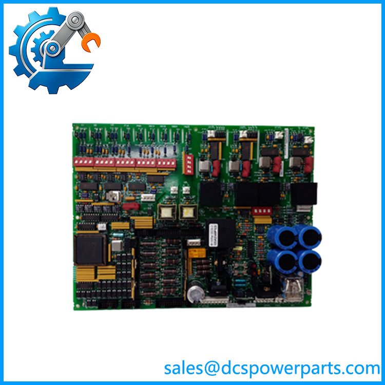
GE DS200DCFBG1BNC DCFB Power Supply / Feedback Board
Product Introduction
The GE DS200DCFBG1BNC is a DCFB Power Supply and Feedback Board from GE’s legacy Mark V DS200 control hardware family. The DCFB board is used across several GE drive and excitation platforms, including DC2000, CB2000, EX2000, FC2000, GF2000, ME2000, and AC2000 applications. Its role is broader than that of a conventional power-supply PCB: it generates control-level DC power while also supporting field/excitation circuitry and monitoring of important AC-line and DC motor or generator signals. GE’s GEI-100028C documentation identifies the DCFB as a dedicated board for these applications.
The GE DS200DCFBG1BNC provides regulated control supplies including +5 VDC, ±15 VDC, and ±24 VDC. The documented G1B configuration includes a +24 VDC supply rated up to 3 A, a -24 VDC supply rated up to 1 A, +15 VDC outputs rated at 0.8 A each, and a +5 VDC output rated at 4 A. The board also contains circuitry associated with motor or generator field excitation, SCR gate-pulse generation, and monitoring of armature current/voltage, field current, AC-line current, and AC-line voltage.
For replacement work, the complete DS200DCFBG1BNC designation is important. The GE manual specifically states that all digits of the board catalog number matter when ordering or replacing a board. The BNC suffix should therefore not be casually replaced with another DCFB suffix simply because the base number appears identical. Before installation, compare connector arrangement, jumper positions, DIP-switch settings, board revision, drive/excitation application, and the original cabinet documentation.
Technical Specifications
| Parameter | Specification |
|---|---|
| Product Model | DS200DCFBG1BNC |
| Manufacturer | General Electric |
| Product Series | Mark V / DS200 |
| Functional Acronym | DCFB |
| Product Type | DC Feedback / Power Supply Board |
| Board Revision | B |
| Hardware Group | G1 |
| Primary Applications | DC2000, CB2000, EX2000, FC2000, GF2000, ME2000, AC2000 |
| Control-Level DC Outputs | +5 VDC, ±15 VDC, ±24 VDC |
| +24 VDC Output | Up to 3 A |
| -24 VDC Output | Up to 1 A |
| +15 VDC Output | 0.8 A each |
| +5 VDC Output | 4 A |
| Auxiliary AC Output | 115 VAC, application-dependent |
| Configurable Jumpers | 12 for documented G1B configuration |
| DIP Switches | 7 |
| Protective Fuses | FU1, FU2, FU3 |
| Status Indicators | 2 red LEDs + 1 neon indicator |
| Test Points | 5 |
| Functional Circuits | Power supply, field/excitation, SCR gate-pulse drive, AC/DC monitoring |
| Reference Manual | GEI-100028C |
| Communication Protocol | None; board-level Mark V control interface |
| Mounting | GE Mark V / DS200 cabinet or rack assembly |
| Operating Temperature | Verify exact cabinet/environmental specification before publication |
| Protection Rating | Determined by installed cabinet/enclosure; not a standalone IP-rated module |
The electrical output ratings above are taken from documentation and technical records for the DCFB G1B board family. The exact BNC variant should still be matched against the original board and cabinet drawings before treating every listed value as an installation-specific rating.
Main Features and Engineering Considerations
1. Multiple control-level power rails
The DCFB supplies several DC rails required by the associated Mark V drive-control electronics. The +5 VDC rail is particularly important because the DCFB documentation describes the /PSEN signal used to indicate whether the +5 V supply is properly regulated. If the supply is not regulated, this signal can cause the associated SDCC/LDCC control processor to reset.
2. Power supply plus feedback functionality
Calling DS200DCFBG1BNC only a “power supply board” misses part of its function. The board also handles signal-conditioning and monitoring functions associated with armature voltage/current, field current, AC-line measurements, and related drive signals. A DCFB fault can therefore appear as a control, feedback, or excitation problem elsewhere in the system.
3. Field and excitation circuitry
The DCFB contains motor or generator field power circuitry and driver circuitry associated with SCR gate-pulse generation. The SCR module itself is excluded from this board’s circuitry. This distinction matters when troubleshooting excitation faults: a failed DCFB should not automatically be assumed to be the source of every SCR firing problem.
4. Configurable jumpers and DIP switches
The G1B board contains configurable hardware. Technical records identify 12 jumpers and 7 DIP switches, with most selections normally established during factory configuration. GE replacement procedures require technicians to compare configuration settings between the removed board and replacement board.
5. Feedback signal conversion and monitoring
The DCFB interfaces with several electrical feedback signals. Documentation describes voltage-controlled oscillator circuitry associated with feedback signals sent toward the SDCC/LDCC control board. DIP-switch settings can affect signal scaling, so incorrect configuration can produce misleading feedback values even when the replacement board is electrically functional.
6. Application-dependent architecture
The same DCFB family appears in multiple GE drive and excitation platforms, but the board’s role can differ between a drive application and an EX2000 excitation application. The original system model and wiring drawings therefore matter when validating a replacement.
Application Scenarios
- GE EX2000 excitation systems
- GE DC2000 drive systems
- GE AC2000 drive systems
- GE CB2000 drive systems
- GE FC2000 drive systems
- GE GF2000 drive systems
- GE ME2000 drive systems
- Industrial DC motor control
- Generator field/excitation control
- Mark V cabinet power distribution
- Legacy GE drive maintenance and replacement
Engineer’s Guide: Field Pitfalls
Do not order by “DS200DCFB” alone. GE explicitly states that all digits of the board number are important for ordering and replacement. The G1BNC configuration should be matched against the installed card.
Do not confuse DCFB with a simple DC feedback card. It performs control-level power conversion as well as feedback and excitation-related functions.
Check the incoming control power first. A failed CPT output, wiring fault, fuse, or upstream supply problem can produce symptoms that resemble a failed DCFB.
Record every jumper and DIP-switch position before removing the old card. Configuration errors can produce incorrect feedback scaling or control behavior even when the replacement PCB powers up normally.
Inspect the fuses. FU1, FU2, and FU3 provide protection for different board circuits. A blown fuse can be a symptom rather than the root cause, so replacing the fuse without investigating the associated circuit can lead to another failure.
Check the associated SDCC/LDCC board. The DCFB and drive-control card exchange power-status and feedback information. A control-card fault can sometimes be mistaken for a DCFB failure.
Verify the connector suffix. The BNC version should not be assumed interchangeable with B, BKC, BLC, or other DCFB variants without engineering confirmation. Technical listings document multiple suffix variants within the DS200DCFBG1B family.
Treat the board as hazardous electrical equipment. The DCFB handles power derived from the control power transformer and includes high-energy electrical circuits. Proper isolation, discharge, voltage verification, and ESD handling are required before removal.
Frequently Asked Questions
What is GE ?
It is a GE Mark V DCFB Power Supply / Feedback Board, used in GE drive and excitation systems. The DCFB provides control-level DC power and contains field/excitation and electrical feedback circuitry.
What does DCFB stand for?
DCFB is the functional acronym used for the DC Feedback / Power Supply Board in the GE DS200 documentation.
What systems use ?
The DCFB G1B family is documented for DC2000, CB2000, EX2000, FC2000, GF2000, ME2000, and AC2000 applications.
What DC voltages does the DCFB generate?
The board generates +5 VDC, ±15 VDC, and ±24 VDC control-level supplies. The documented G1B ratings include +5 VDC at 4 A, +24 VDC at up to 3 A, -24 VDC at up to 1 A, and +15 VDC outputs at 0.8 A each.
Does communicate through Ethernet or Modbus?
No. This is a board-level control and power interface within the GE Mark V architecture. It is not an Ethernet, Modbus, PROFIBUS, or standalone PLC communication module.
Is compatible with Mark VI?
It should not be treated as a Mark VI replacement. The belongs to the legacy Mark V / DS200 hardware family. A Mark VI or Mark VIe application requires its own hardware architecture and compatibility verification.
What should be checked before replacing the board?
Verify the complete part number, board revision, connector/suffix configuration, drive or excitation model, jumper settings, DIP-switch settings, incoming control power, fuses, associated SDCC/LDCC card, and all connected wiring.
Procurement Note
Specify the replacement as:
GE General Electric — DCFB — Mark V — G1B — Revision B — Power Supply / Feedback Board
For a field replacement, I would treat the BNC suffix as a hard procurement constraint until the original GE cabinet documentation confirms an approved substitute. The DCFB family contains multiple suffix configurations, and GE’s own manual emphasizes that the complete board number is important for replacement.
The practical acceptance check should include visual inspection of the PCB revision and connectors, jumper/DIP-switch comparison, fuse inspection, insulation and wiring checks, verification of the generated DC rails, and functional confirmation of the associated drive or excitation system after installation.