Description
Product Introduction
Contactor-control faults in turbine and industrial drive cabinets can prevent equipment from starting, stopping, or switching as commanded. Correct diagnosis requires checking the driver board, contactor coil, control signals, and associated power circuitry rather than replacing components based on symptoms alone.
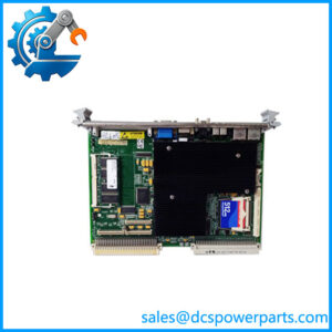
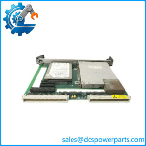
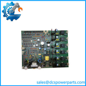
The GE DS200CDBAG1ABA CDBA board provides the contactor-driving function within compatible GE control equipment. The CDBA board family uses a controlled drive-current arrangement to operate the contactor and includes diagnostic test points for maintenance checks. Verify the exact board revision and system wiring before installation.
Key Technical Specifications
| Parameter | Details |
|---|---|
| Product Model | DS200CDBAG1ABA |
| Manufacturer | General Electric |
| Functional Acronym | CDBA |
| Product Type | Contactor Driver Board |
| Control System | GE Mark V Speedtronic; related drive applications require confirmation |
| Main Function | Controls compatible contactor opening and closing |
| Related Power/Control Boards | DS200DCFB, DS200SDCI, depending on system configuration |
| Contactor coil voltage | 30–40 VDC is documented for the CDBA family |
| Closing drive | Family documentation describes a 105 VDC pulse for approximately 250 ms |
| Holding-current adjustment | RV1 potentiometer on documented board variants |
| Diagnostic test points | Three reported on documented variants |
| Board reference supply | +15 VDC test point, with ±20% tolerance reported for DS200CDBAG1A |
| Fuse | 4 A, 125 V, 2AG slow-blow fuse reported for the board family |
| Connector arrangement | 1TB connector sections identified as 1TBA, 1TBB, 1TBC, and 1TBD on documented variants |
| Instruction Manual | GEI-100182B |
| Installation | Internal control-cabinet PCB; follow the equipment-specific mounting and wiring instructions |
| Exact revision compatibility | Must be verified against the full model and system documentation |
Specification caution: The detailed electrical figures above are documented for the CDBA board family and related catalog variants, not independently verified against every suffix character in DS200CDBAG1ABA. Confirm them against the applicable manual and installed hardware before use.
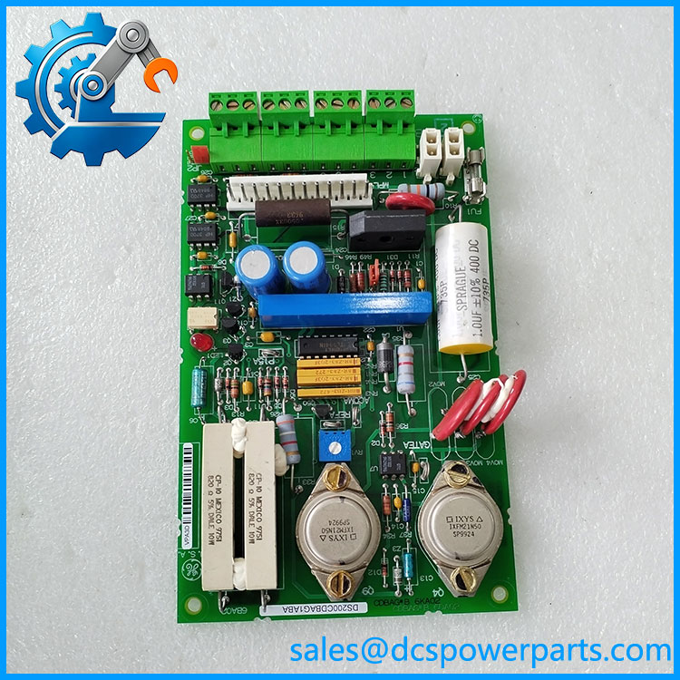
DS200CDBAG1ABA
Major Features and Advantages
Controlled contactor operation: The CDBA board provides the drive function needed to operate a compatible contactor. Documentation for the family describes a higher-voltage closing pulse followed by regulated drive current to maintain the contactor in its commanded state. Actual operating conditions depend on the installed configuration.
Adjustable drive current: The RV1 potentiometer is identified in documentation for related CDBA variants as the contactor-drive current adjustment. During replacement, record the original setting and follow the prescribed adjustment procedure. An incorrect setting may affect contactor operation or coil performance.
Diagnostic test points: Three test points are documented on related CDBA assemblies, including the board common reference, +15 VDC supply reference, and contactor-driver reference. These points help qualified technicians check board conditions during troubleshooting. Use the correct reference point and measurement procedure specified in the manual.
Serviceable hardware: The documented assembly includes a fuse, connectors, and factory or application-related jumper positions. These features support inspection and maintenance, but fuse replacement or jumper changes should follow the applicable instructions rather than assumptions based on another revision.
Legacy system support: For facilities maintaining installed GE Mark V equipment, matching the original board number and configuration can reduce unnecessary changes to cabinet wiring and control logic. A similar catalog number alone does not establish interchangeability.
Application Scenarios and Common Faults
- Turbine-control contactor faults: Investigate the board when a contactor does not respond correctly to a command, while also checking coil condition and control signals.
- Industrial drive maintenance: Confirm that the board matches the installed drive and its associated power-supply circuitry before replacement.
- Planned shutdown work: Verify the replacement’s revision, condition, connector arrangement, and test documentation before the maintenance window.
- Intermittent contactor operation: Check the specified driver reference, adjustment setting, wiring, and contactor coil rather than assuming the PCB is the sole cause.
Field warning: A blown fuse may indicate a downstream fault or an abnormal load. Replacing the fuse without finding the cause can result in another failure.
Related GE Parts
| Model | General identification |
|---|---|
| DS200CDBAG1A | CDBA contactor driver board, related catalog variant |
| DS200CDBAG1B | CDBA contactor driver board with a different functional revision |
| DS200DCFBG1B | DC power and feedback board |
| DS200SDCI | DC power supply and instrumentation board family |
| DS200CPCAG1A | Contactor pilot card; verify its role in the particular system |
| DS200DCCAG4 | Drive control card; verify the exact application and revision |
These parts are related by control-system context, not necessarily by direct replacement compatibility. Confirm the equipment bill of materials and the complete model number before substituting any board.
Engineer’s Guide: Before Ordering or Installation
1. Verify the full part number. Check the PCB label for DS200CDBAG1ABA, along with the base catalog number, functional revision, and any additional assembly markings.
2. Record the original configuration. Photograph the connector locations, jumper positions, and RV1 potentiometer setting before removal. Do not assume that settings from a different revision are applicable.
3. Inspect the complete contactor circuit. Check the contactor coil, associated wiring, control command, supply circuitry, and fuse condition before declaring the board defective.
Safety requirement: Isolate the drive, verify the absence of hazardous voltage, and use appropriate electrostatic-discharge precautions before handling the PCB. Follow the equipment-specific service manual for measurements and adjustments.
Frequently Asked Questions
What is the GE DS200CDBAG1ABA used for?
It is identified as a CDBA contactor driver board used in GE turbine-control and related drive equipment. Its function is to control the opening and closing of a compatible contactor.
What voltage does the CDBA board apply to close a contactor?
Documentation for related CDBA variants describes a 105 VDC pulse lasting approximately 250 milliseconds to force the contactor closed, followed by regulated holding current. Verify the procedure and values for the exact installed revision before testing.
What is the purpose of the RV1 potentiometer?
On documented CDBA variants, RV1 adjusts the contactor-driver current. Preserve the original setting and use the applicable service instructions when installing or calibrating a replacement.
Can DS200CDBAG1ABA replace DS200CDBAG1A or DS200CDBAG1B?
Do not assume direct interchangeability from the shared CDBA designation. Compare the full part numbers, revisions, assembly details, and equipment documentation before approving a replacement.
What should be checked if the contactor fails to operate?
Check the control command, wiring, contactor coil, driver supply, fuse, and documented test points. Follow the correct measurement procedure and use the board’s specified common reference. A contactor fault does not by itself prove that the driver board has failed.
What information should buyers request for a used or refurbished board?
Request photographs of the actual board label, confirmation of the complete model and revision, a description of its condition, test results where available, warranty terms, and the expected dispatch lead time.
Which manual is associated with this board?
GEI-100182B is referenced for the CDBA Contactor Driver Board family. Confirm that the manual covers the installed revision and application before using it for adjustment or replacement work.
Recommended product listing title: GE CDBA Contactor Driver Board for Mark V Control Systems