Description
Product Overview
The GE Multilin 869-E-P1-P1-B1-H-S-S-A-L-A-M-M-P-F-B-SE-N-N-B-N-1 is a fully configured Multilin 869 motor protection and management relay intended for medium- and large-motor applications. The 869 platform combines protection, control, monitoring, and motor diagnostics in one relay, covering induction and synchronous motors as well as applications involving VFD operation, high-inertia loads, cyclic loading, and demanding starting conditions. This particular configuration uses P1 5 A phase-current inputs and a B1 5 A ground-current arrangement, making the exact CT secondary arrangement an important installation check.
For GE Multilin 869-E-P1-P1-B1-H-S-S-A-L-A-M-M-P-F-B-SE-N-N-B-N-1, the option string defines much of the actual hardware and functionality, so the complete catalog number should be retained during procurement. The documented configuration provides 8 configurable digital inputs, 8 Form C digital outputs, 4 universal analog inputs, and 2 analog outputs, together with an 85–265 VAC / 100–250 VDC power supply. Its protection functions include phase, negative-sequence, ground, thermal, stator differential, directional, voltage, frequency, volts-per-hertz, out-of-step, and field-failure elements.
The GE Multilin 869-E-P1-P1-B1-H-S-S-A-L-A-M-M-P-F-B-SE-N-N-B-N-1 is more than a conventional overload relay. It can provide motor-start records, disturbance recording, acceleration-time information, mechanical-jam detection, broken-rotor-bar detection, and other motor-condition data. Communication options can support integration with plant control and monitoring systems, including IEC 61850 and other industrial protocols depending on the installed option set.
For a replacement project, the complete option code matters. A visually identical 869 relay with different CT inputs, power supply, I/O, or communications can require significant wiring and configuration changes.
Product Introduction
A motor relay becomes difficult to replace when the CT arrangement, I/O count, and communications are embedded in the original specification. 869-E-P1-P1-B1-H-S-S-A-L-A-M-M-P-F-B-SE-N-N-B-N-1 combines 5 A current inputs with 8 digital inputs, 8 Form C outputs, 4 universal analog inputs, and 2 analog outputs.
For a GE Multilin 869 motor protection relay replacement, match the complete option string—not just “869.” CT secondary ratings, ground-fault arrangement, supply voltage, I/O configuration, firmware, and communications should all be checked before commissioning.
Key Technical Specifications
| Parameter | Value |
|---|---|
| Manufacturer | GE Multilin |
| Product Family | Multilin 869 |
| Full Model | 869-E-P1-P1-B1-H-S-S-A-L-A-M-M-P-F-B-SE-N-N-B-N-1 |
| Product Type | Motor Protection & Management Relay |
| Motor Applications | Medium/large induction and synchronous motors |
| Phase CT Input | 5 A |
| Ground CT Input | 5 A + CBCT configuration |
| Voltage Inputs | 120/240 VAC nominal; configuration-dependent VT inputs |
| Frequency | 50/60 Hz nominal |
| Digital Inputs | 8 configurable |
| Digital Outputs | 8 Form C |
| Analog Inputs | 4 universal |
| Analog Outputs | 2 × 4–20 mA |
| Digital Output Rating | 5 A, 250 VAC / 30 VDC |
| Power Supply | 85–265 VAC / 100–250 VDC |
| Protection Functions | 50/51, 49, 87S, 67, 59, 24, 81, 78, 86, 90F and related elements |
| Communications | Modbus, DNP3, IEC 60870-5-103/104, IEC 61850; configuration-dependent |
| Motor Diagnostics | Start records, disturbance records, acceleration monitoring, mechanical-jam and rotor-bar diagnostics |
| Mounting | Draw-out relay construction |
| Operating Temperature | -25°C to +70°C |
| Storage Temperature | -40°C to +85°C |
| Front Protection | IP30 |
| Approx. Weight | 3.2 kg |
The exact option configuration determines which functions and interfaces are physically present, so generic 869 specifications should not be substituted for the complete catalog configuration.
Related Products
- GE Multilin 869 — The base motor protection platform. The exact option code determines CT inputs, I/O, communications, power supply, and other installed functions.
- 869-E-P1-P1-B1-H-H-S-A-A-M-M-I-I-SE-SE-N-B-B-1 — Another 869 configuration with different I/O and communications options. It should not be treated as a direct drop-in replacement without a configuration comparison.
- GE Multilin 850 — Generator and motor protection platform used for broader rotating-machine protection applications. Its protection philosophy differs from the motor-focused 869.
- GE Multilin 845 — Transformer protection platform. It shares the Multilin relay ecosystem but is not a motor-relay substitute.
- GE Multilin 750/760 — Earlier-generation feeder/motor protection platforms that may appear in legacy plants. Application and hardware architecture differ from the 869.
- 5 A Phase CT System — Required for the P1 phase-current configuration. CT ratio, burden, polarity, and wiring should be verified against the installed motor protection scheme.
- Core-Balance CT — Relevant to the B1 ground-current configuration. The actual CBCT arrangement should be checked before field termination.
- IEC 61850 Communication Architecture — Applicable where the configured 869 includes the corresponding communications capability. Network engineering and relay configuration must match the plant’s station-bus design.
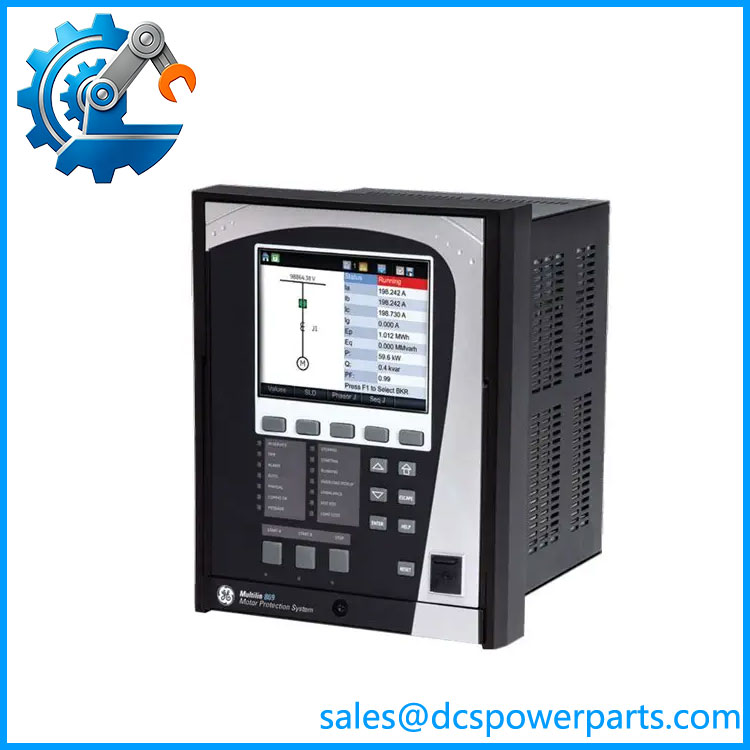
869-E-P1-P1-B1-H-S-S-A-L-A-M-M-P-F-B-SE-N-N-B-N-1
Frequently Asked Questions
What is GE Multilin 869-E-P1-P1-B1-H-S-S-A-L-A-M-M-P-F-B-SE-N-N-B-N-1 used for?
It is a motor protection and management relay for medium- and large-size motors.
Typical applications include:
- Large induction motors
- Synchronous motors
- VFD-driven motors
- High-inertia motor loads
- Pumps and compressors
- Fans and blowers
- Mills and conveyors
- Cyclic-load motor applications
Its protection functions cover electrical faults as well as thermal and mechanical operating conditions.
What does P1-P1-B1 mean in this 869 configuration?
The option string should be interpreted as part of the relay’s ordered configuration rather than as a generic model suffix.
For this unit, available documentation identifies:
- P1: 5 A phase-current input configuration
- P1: 5 A current-input configuration associated with the second current channel group
- B1: 5 A ground-current / CBCT configuration
The exact terminal mapping should be confirmed against the relay’s hardware documentation before wiring.
Does this 869 relay support 5 A CTs?
Yes. The specified configuration uses 5 A phase-current inputs and a 5 A ground-current arrangement.
Before commissioning, check:
- CT secondary rating.
- CT ratio.
- CT polarity.
- CT grounding.
- Phase sequence.
- Ground/CBCT wiring.
- Relay CT configuration.
CT wiring errors are not something to troubleshoot casually on a large energized motor.
What protection functions are available?
The configured 869 platform provides a broad protection set, including:
- Phase overcurrent
- Negative-sequence protection
- Ground/neutral overcurrent
- Thermal overload
- Stator differential
- Directional overcurrent
- Overvoltage
- Under/overfrequency
- Volts-per-hertz
- Out-of-step
- Start inhibit
- Field-failure protection
The exact enabled elements depend on the relay configuration and application settings.
Can I use this 869 for a VFD-driven motor?
The Multilin 869 platform supports VFD-driven motor applications, but the suitability of a particular installation depends on the drive topology, CT/VT arrangement, motor data, starting method, and selected protection elements.
For a VFD application, do not copy settings from a direct-on-line motor simply because the motor rating is identical. The current waveform and operating profile can be materially different.
Does this relay support IEC 61850?
The 869 platform supports IEC 61850, along with other communication protocols such as Modbus and DNP3. However, the complete option string determines which communication hardware and functions are actually fitted.
For a replacement, verify the station-bus configuration, firmware, relay communication settings, and required IEC 61850 services before removing the existing relay.
Will replacing the 869 erase my motor protection settings?
The replacement relay does not automatically inherit the configuration of the old relay.
Before replacement, back up and document:
- Motor nameplate data
- CT and VT ratios
- Protection settings
- Motor thermal model
- Starting parameters
- I/O assignments
- Trip logic
- Communication settings
- IEC 61850 configuration, if applicable
- Firmware revision
A replacement relay should be configured and bench-tested before connection to the live motor protection circuit.
Can I hot-swap this Multilin 869?
The 869 uses a draw-out construction, which simplifies maintenance and relay removal, but that does not mean the relay should automatically be withdrawn under energized conditions.
The safe procedure depends on the switchgear design, CT shorting arrangement, trip circuit, VT isolation, and plant maintenance rules. In particular, CT circuits must be handled correctly; opening an energized CT secondary can create dangerous voltage.
Does the 869 support motor diagnostics?
Yes. The platform provides diagnostic functions beyond conventional electrical protection, including motor-start records, disturbance recording, acceleration monitoring, broken-rotor-bar detection, and mechanical-jam detection.
These records can be useful when determining whether a repeated motor trip originates from electrical protection, abnormal starting behavior, or a mechanical problem.
How should a New Surplus 869-E-P1-P1-B1-H-S-S-A-L-A-M-M-P-F-B-SE-N-N-B-N-1 be tested?
A proper acceptance test should reproduce the relay’s actual protection environment as closely as practical.
Recommended sequence:
- Verify the complete catalog number character by character.
- Record serial number, hardware revision, and firmware.
- Confirm the 5 A CT input configuration.
- Verify the B1 ground-current arrangement.
- Power the relay using the specified supply range.
- Check self-diagnostics and display operation.
- Test representative current and voltage inputs.
- Exercise digital inputs and Form C outputs.
- Verify the 4 analog inputs and 2 analog outputs.
- Test selected protection elements using secondary injection.
- Verify trip/alarm logic.
- Test communication ports and required protocol services.
- Confirm event and disturbance recording.
- Compare all settings against the approved motor-protection file.
- Record the complete test report before plant installation.
Procurement note: for this specific 869 configuration, the long option string is the specification. Do not accept a quote simply stating “GE Multilin 869” as an equivalent. The P1/P1/B1, H/S/S, A/L/A, M/M, power-supply, and communication options need to be matched against the existing relay.