Description
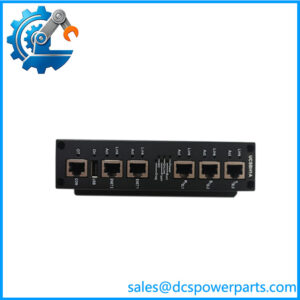
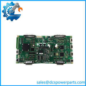
GE Multilin 469-P5-HI-AI-T Motor Management Relay
Product Overview
The GE Multilin 469-P5-HI-AI-T belongs to the Multilin 469 family of microprocessor-based motor management relays developed for protection and monitoring of medium- and large-size motors. The 469 combines electrical protection, thermal modeling, motor starting supervision, metering, RTD monitoring, programmable logic, and communications in a single protection platform. The P5 configuration identifies 5 A phase CT secondaries, while HI specifies the high-range control-power supply of 90–300 VDC or 70–265 VAC at 48–62 Hz. GE documentation also identifies the T option as an enhanced display configuration with 10Base-T Ethernet communication.
For an installed motor protection system, the GE Multilin 469-P5-HI-AI-T sits between the motor’s instrument transformers, RTDs, contactors or breaker controls, and the plant supervisory network. It is not a PLC I/O module. Its protection functions include thermal overload protection, phase and ground overcurrent, current unbalance, voltage protection, underfrequency, mechanical jam, acceleration/start supervision, power measurement, and motor thermal modeling. The relay can also monitor RTDs and provide programmable analog outputs, depending on the exact order configuration.
One procurement point needs special attention: AI does not match the standard GE 469 analog-output designators shown in the published order-code documentation. The documented choices are A1 for four 0–1 mA analog outputs and A20 for four 4–20 mA analog outputs. Before purchasing a replacement, compare the complete nameplate and original order documentation rather than assuming AI means A1 or A20. That small character difference can change the external control-system interface.
Product Introduction
Motor protection becomes difficult when the relay is doing more than simple overcurrent. The Multilin 469 combines CT measurement, thermal modeling, starting supervision, RTD inputs, voltage measurement, power functions, and communications in one protection platform.
For legacy motor protection replacement, the phase-CT rating, control-power range, analog-output configuration, Ethernet option, firmware, and stored motor settings should all be checked before energizing the replacement relay.
Key Technical Specifications
| Parameter | Specification |
|---|---|
| Product Model | 469-P5-HI-AI-T |
| Manufacturer | GE Multilin / GE Digital Energy |
| Product Series | Multilin 469 |
| Product Type | Motor Management Relay |
| Phase CT Configuration | P5 — 5 A phase CT secondaries |
| Control Power | HI |
| DC Control Power Range | 90–300 VDC |
| AC Control Power Range | 70–265 VAC |
| AC Frequency | 48–62 Hz |
| Ethernet Option | T — enhanced display with 10Base-T Ethernet |
| Analog Output Code | AI requires verification |
| Documented A1 Option | Four 0–1 mA analog outputs |
| Documented A20 Option | Four 4–20 mA analog outputs |
| Phase Current Inputs | 1 A or 5 A secondary architecture; P5 specifies 5 A |
| Ground CT Inputs | Core-balance CT and 1 A/5 A ground CT arrangements supported |
| VT Connection | Delta or wye |
| Communications | RS-232 / RS-485; Ethernet when T option is fitted |
| Ethernet | 10Base-T |
| Protocol | Modbus RTU; Ethernet functions depend on installed option/software |
| Analog Input Range | 0–1 mA, 0–20 mA, or 4–20 mA configurable for applicable inputs |
| Analog Input Impedance | 226 Ω ±10% |
| Analog Input Accuracy | ±1% full scale |
| Typical Power | 25 VA |
| Maximum Power | 45 VA |
| Front Interface | LCD/keypad, enhanced display on T configuration |
| Engineering Software | EnerVista 469 Setup |
| Protection Functions | Thermal, overcurrent, voltage, current unbalance, starting, jam, RTD and power-related functions |
| Mounting | Panel / switchgear relay mounting |
| Status | Legacy product; exact lifecycle depends on installed market and support channel |
The basic 469 documentation confirms the P5, HI, analog-output, display, and Ethernet order-code structure.
Major Features / Practical Advantages
1. 5 A Phase CT Architecture
The P5 designation specifies 5 A phase CT secondaries. This matters when replacing an existing relay because the phase CT wiring and relay configuration must correspond to the actual secondary rating. The 469 can be configured around 1 A or 5 A CT systems, but a P5 unit should not be treated as an arbitrary 1 A replacement simply because the relay family is the same.
2. High-Range Control Power
The HI option accepts 90–300 VDC or 70–265 VAC at 48–62 Hz. This makes the configuration suitable for many conventional switchgear control-power systems. The 469 documentation specifies approximately 45 VA maximum consumption and 25 VA typical consumption.
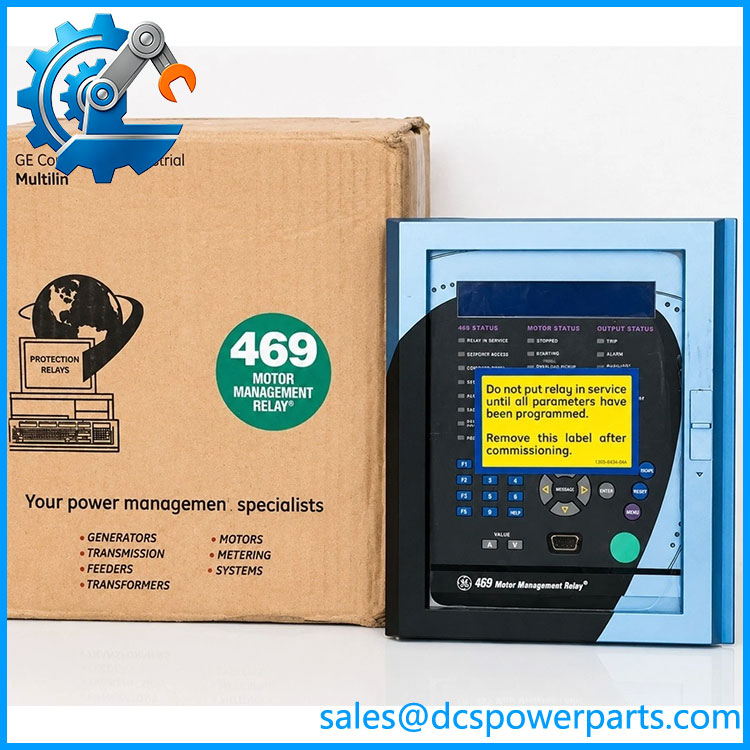
469-P5-HI-AI-T
3. Motor Thermal Protection
The 469 uses an integrated motor thermal model rather than relying only on instantaneous current thresholds. Rotor and stator heating, cooling behavior, current loading, and negative-sequence effects contribute to motor thermal protection. This is particularly relevant on high-inertia motors where a conventional overload relay can miss the relationship between starting duration and accumulated thermal capacity.
4. Starting and Mechanical Protection
The platform provides start supervision and inhibit functions, acceleration-related protection, mechanical jam detection, voltage-compensated acceleration, and reduced-voltage starting control in applicable configurations. For large motors, these functions can be more important during startup than ordinary running-current protection.
5. Ethernet Communication
The T option identifies the enhanced-display version with 10Base-T Ethernet. GE’s documentation specifically uses the T suffix for the Ethernet-equipped version. Ethernet status can be viewed through the relay’s network-status diagnostics.
6. Analog Signal Integration
The 469 supports four analog outputs, but the actual electrical range depends on the order code. A1 represents four 0–1 mA outputs, while A20 represents four 4–20 mA outputs. Because the supplied code contains AI, this is one of the first items that should be verified from the physical nameplate. Do not wire a DCS analog input based on an assumed interpretation.
7. RTD and Motor Condition Monitoring
The 469 supports RTD-based monitoring for motor thermal conditions and other connected temperature points. Available measurements can include stator, bearing, and additional RTD temperatures. This allows the relay to combine electrical loading information with actual machine temperature rather than relying exclusively on CT measurements.
8. Ground-Fault Measurement
The 469 provides a dedicated core-balance ground-current input and a ground CT input compatible with 1 A or 5 A secondary arrangements. GE also specifies dedicated HGF-series CTs for sensitive ground-fault detection. CT selection and grounding topology therefore need to be preserved during replacement.
Related Products
- 469-P5-HI-A20-E — 5 A phase CT, high-range control power, four 4–20 mA analog outputs, enhanced display.
- 469-P5-HI-A20-T — 5 A phase CT and high-range control power with the T Ethernet option and enhanced display.
- 469-P5-HI-A1-T — 5 A phase CT, high-range power, four 0–1 mA analog outputs, enhanced display with Ethernet.
- 469-P1-HI-A20-E — 1 A phase CT configuration with high-range control power and 4–20 mA analog outputs.
- 469-P1-LO-A20-E — 1 A phase CT configuration with low-range control power and 4–20 mA analog outputs.
- 469-P5-LO-A20-T — 5 A phase CT, low-range control power, 4–20 mA outputs, and Ethernet.
- SR469-P5-HI-A20-T — cased version of the 469 family with 5 A phase CTs, HI control power, 4–20 mA outputs, and Ethernet.
- 489-P5-HI-A20 — related GE Multilin motor/generator management platform with 5 A CT inputs and high-range control power.
- 369-HI-R-M-0-0 — earlier GE Multilin motor protection platform with a different architecture and order-code system.
The related 469 configurations are based on GE’s documented P1/P5, LO/HI, A1/A20, E/T/D, and H ordering structure.
FAQ
Can I replace a 469-P5-HI-AI-T with a 469-P5-HI-A20-T?
Not without checking the original unit. The standard GE documentation identifies A20 as four 4–20 mA outputs, whereas AI is not shown as a standard analog-output designator. Verify the physical nameplate and original order record first.
Does the T suffix mean Ethernet?
Yes. In the GE 469 ordering structure, T means enhanced display with Ethernet (10Base-T). The E option is the enhanced display without that Ethernet designation.
Is the P5 version compatible with 5 A CTs?
Yes. P5 identifies the 5 A phase-CT-secondary configuration. The 469 also supports field-programmable 1 A/5 A arrangements for certain ground-current circuits, but the phase CT order option remains an important procurement identifier.
Does the 469 support Modbus?
The 469 provides serial communications including RS-232 and isolated RS-485 interfaces, with Modbus RTU support documented for the platform. Ethernet capability is associated with the T option. Exact network mapping should be recovered from the existing relay configuration before replacement.
Does this relay support firmware v3.1?
Do not assume it. The available GE 469 documentation identifies software revisions separately; one published instruction manual is for software revision 5.0x. Firmware should be verified from the installed relay rather than inferred from the part number.
Can I hot-swap the relay?
The 469 uses a withdrawable/cased architecture in applicable installations, and the case incorporates mechanisms that short certain CT circuits when the relay is withdrawn. That does not mean unrestricted energized removal is acceptable. Follow the approved switchgear and CT-isolation procedure before withdrawing the relay.
Will replacing the relay preserve the motor protection settings?
Do not assume it will. Motor full-load current, CT ratios, thermal model constants, acceleration/start settings, RTD assignments, trip logic, voltage settings, ground-fault parameters, analog mappings, and communication settings must be backed up and verified. The EnerVista 469 Setup software is the engineering environment associated with the relay.
Is the 469 suitable for PLC or DCS control?
It is better described as a motor management and protection relay with control-system interfaces, not as a PLC. A DCS can receive measurements, alarms, status, and selected control signals, while the 469 retains dedicated motor protection functions.
Procurement Note
The biggest issue with the supplied 469-P5-HI-AI-T designation is the AI segment. GE’s published 469 ordering table lists A1 and A20, not AI: A1 corresponds to four 0–1 mA outputs, while A20 corresponds to four 4–20 mA outputs. Before purchasing or wiring a replacement, inspect the relay nameplate and compare the complete order code.
For a legacy replacement, record the existing relay’s phase CT ratio, ground CT arrangement, VT connection, motor full-load current, thermal model settings, start profile, RTD mapping, trip outputs, analog assignments, Ethernet settings, and stored protection configuration.
For New Surplus equipment, unused physical condition does not establish configuration compatibility. A relay that powers up correctly can still contain unsuitable motor settings or an incompatible analog-output configuration. In this particular case, the nameplate/order-code verification should happen before any commercial acceptance decision.