Description
GE Multilin 350-LP5G5HEENNSNDN Feeder Protection Relay
Product Overview
The GE Multilin 350-LP5G5HEENNSNDN belongs to the Multilin 350 feeder protection platform, a microprocessor-based protection system designed for primary or backup protection of low- and medium-voltage distribution feeders. The 350 family combines protective functions with measurement, event recording, diagnostics, programmable logic, and feeder control. GE documentation describes the 350 as part of the Multilin 3 Series and specifically positions it for feeder protection applications in electrical distribution systems.
For engineers maintaining older switchgear, the GE Multilin 350-LP5G5HEENNSNDN is better viewed as a complete protection IED than as a simple overcurrent relay. Depending on the exact 350 configuration, the platform provides phase and ground overcurrent protection, thermal protection, directional elements, breaker failure functions, cold-load pickup logic, metering, event records, programmable inputs and outputs, and communication interfaces. The corresponding 5 A configuration is intended for conventional CT secondary circuits.
One procurement issue deserves attention: public references identify the exact compact string LP5G5HEENNSNDN, but the standard GE ordering documentation is normally presented in a longer hyphenated format. Because the compact form does not have a sufficiently authoritative character-by-character decoding available, the page does not assign unsupported meanings to every suffix. The relay nameplate, wiring diagram, and complete GE order code should control the final compatibility decision.
Product Introduction
A feeder relay replacement is not just a matter of matching CT current. The protection curve, trip logic, breaker control, communication mapping, and stored settings all affect how the replacement behaves in service. The GE Multilin 350-LP5G5HEENNSNDN belongs to a platform designed to combine those functions inside one feeder protection IED.
For a legacy feeder protection replacement, the practical check is the complete order code plus the existing settings file. The 350 family has multiple hardware and communication configurations, so a visually identical relay can still be functionally different.
Key Technical Specifications
| Parameter | Specification |
|---|---|
| Product Model | 350-LP5G5HEENNSNDN |
| Manufacturer | GE Multilin |
| Product Series | Multilin 350 |
| Product Type | Feeder Protection System |
| Primary Application | Low- and medium-voltage feeder protection |
| Phase CT Input | 5 A configuration indicated by P5 |
| Ground CT Input | 5 A configuration indicated by G5 |
| Power Supply | High-voltage AC/DC configuration |
| Construction | Drawout architecture in applicable 350 configurations |
| Protection | Phase and ground overcurrent, thermal and additional feeder functions depending configuration |
| Control | Programmable feeder control and logic |
| Monitoring | Electrical metering, diagnostics and event recording |
| Communication | Configuration-dependent serial / service communication |
| Engineering Software | GE Multilin EnerVista SR3 family |
| Installation | Switchgear / protection-panel mounting |
| Status | Legacy product |
The 350 platform supports 5 A CT configurations, and documented high-voltage variants use approximately 125–250 VDC / 100–240 VAC supply ranges. The exact compact order string supplied here should still be checked against the relay nameplate before those values are used for installation.
Major Features / Practical Advantages
1. Feeder-focused protection architecture
The Multilin 350 was designed specifically around feeder protection rather than generic automation I/O. Its protection engine handles electrical quantities from CT and, where configured, VT inputs and applies programmable protection elements to those measurements.
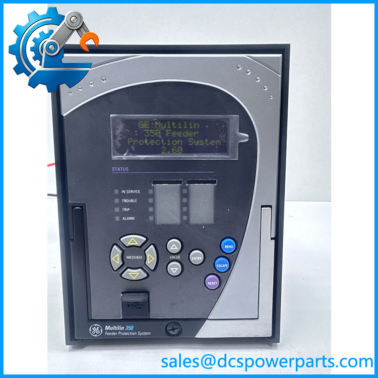
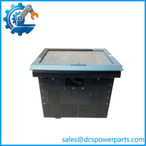
350-LP5G5HEENNSNDN
2. Phase and ground fault protection
The platform provides phase and ground overcurrent protection, including instantaneous and time-overcurrent elements. Depending on the ordered function package, directional protection can also be used to distinguish forward and reverse faults.
That distinction matters on interconnected distribution systems. A relay configured for simple radial feeder protection should not automatically be treated as equivalent to one commissioned with directional elements.
3. Thermal protection
The 350 platform includes a thermal model that can protect feeder cables and associated electrical equipment against prolonged excessive loading. This is different from instantaneous overcurrent protection: the thermal model considers accumulated heating rather than responding only to a high fault-current magnitude.
4. Cold-load pickup capability
After a feeder has been de-energized for an extended period, energization can produce temporarily elevated current from connected loads. The 350 provides cold-load pickup logic that can block or modify selected protection elements during this period.
For retrofit work, this setting should be preserved carefully. Losing cold-load pickup settings can create nuisance trips immediately after a feeder restoration.
5. Programmable logic
The 350 platform provides programmable logic for functions such as interlocking, manual control, and protection-related control sequences. GE documentation identifies 16 logic elements for applications including manual control and peer-to-peer tripping.
6. Event and disturbance information
Protection operation is much easier to diagnose when the relay retains time-stamped events and measured values. The 350 architecture provides event logging and monitoring functions that help maintenance personnel establish what the relay actually detected before a trip.
7. Drawout maintenance concept
Applicable 350 configurations use a drawout construction that simplifies relay replacement and testing compared with permanently wired protective relays. Even with a drawout case, however, do not interpret the mechanical drawout design as permission to remove an energized protection relay. CT circuits, trip circuits, and breaker control wiring require an approved isolation procedure.
8. Communications for substation integration
350-series configurations can provide serial communications for integration with supervisory or plant systems. Depending on the exact ordered communication option, protocols may include Modbus RTU, DNP3.0, or IEC 60870-5-103.
The communication configuration should be checked rather than inferred from the family name.
Related Products
- GE Multilin 350-E-P5-G5-H-E-E-N-N-1E-D-N — Comparable 350 feeder configuration with 5 A phase and ground inputs; useful for comparison when checking communication and option differences.
- GE Multilin 350-E-P5-G5-H-E-S-N-N-SN-D-N — Closely related 5 A high-voltage feeder configuration with standard communication options; useful as a hardware/configuration comparison, not an automatic substitute.
- GE Multilin 350-E-P5-G5-H-E-S-N-M-1E-D-N — 350 configuration with standard communication and Modbus-oriented implementation.
- GE Multilin 350-E-P1-G1-H-E-S-N-M-3E-D-N — 1 A phase/ground CT variant with a different configuration structure.
- GE Multilin 350-E-P5-S5-H-E-S-N-P-1E-N-H — Another 350 feeder configuration with substantially different option coding.
- GE Multilin 339 — Motor protection platform sharing the Multilin 3 Series family concept but intended for motor applications rather than general feeder protection.
- GE Multilin F35 — Feeder protection IED in the broader Multilin platform for applications requiring a different feature and communication architecture.
- GE Multilin F60 — Feeder protection relay for more advanced feeder protection requirements.
- GE Multilin F650 — Feeder protection and bay-control platform with a different hardware and automation architecture.
- GE Multilin 750 — Feeder management relay family for applications requiring broader feeder management and control functions.
FAQ
What is the GE Multilin 350- used for?
It is a feeder protection relay intended for electrical distribution protection, monitoring, and control. The 350 family can be applied as primary or backup protection for distribution feeders.
Is this a PLC or DCS I/O module?
No. It is a dedicated electrical protection IED. It measures electrical quantities from CT/VT circuits, executes protection algorithms, operates relay outputs, records events, and communicates with supervisory systems.
What does the P5/G5 configuration indicate?
In the standard 350 ordering structure, P5 identifies a 5 A phase-current input configuration and G5 identifies a 5 A ground-current input configuration. The compact LP5G5... notation supplied here is not sufficiently documented to decode the leading L independently, so it should not be assigned an unsupported meaning.
Can I hot-swap the 350 relay?
Do not assume energized hot replacement is acceptable. Although the 350 platform uses drawout construction in applicable configurations, CT circuits can develop hazardous voltages when improperly disconnected and breaker trip circuits can create an unintended operation. Follow the site’s protection-relay isolation procedure.
Does it support Modbus RTU?
The 350 family has configurations supporting Modbus RTU, as well as other communication protocols such as DNP3.0 and IEC 60870-5-103. The exact protocol available on must be confirmed from its complete order code and communication hardware.
Does this exact relay support firmware v3.1?
That cannot be established from the part number alone. Firmware revision is a separate verification item and should be read from the relay or confirmed through the applicable GE engineering software before planning a replacement.
Can I replace another Multilin 350 with this model?
Only after comparing the complete order codes. Check CT ratings, VT availability, protection function package, control options, communications, I/O, environmental coating, power supply, and stored settings. The 350 family contains many configuration variants that are similar externally but not functionally identical.
Will the protection settings remain after replacement?
Do not assume that a replacement relay contains the original feeder settings. Back up the existing relay configuration before removal whenever possible. Verify phase/ground CT ratios, pickup values, time curves, directional settings, breaker-failure logic, cold-load pickup, output assignments, communications, and event-record configuration during commissioning.
Procurement Note
The should be purchased by complete configuration, not merely by the words “Multilin 350.” The exact compact identifier is found in current secondary inventory records, while GE documentation generally presents the 350 order code in a longer segmented form. That difference is why the full nameplate and order-code label should be retained as the controlling procurement reference.
For New Surplus or refurbished inventory, verify the front display, keypad, rear terminal arrangement, drawout mechanism, CT/VT input markings, auxiliary supply marking, communication ports, and relay revision. A power-up test is useful, but it does not prove that the relay’s protection settings or communication configuration match the removed unit.
Before commissioning, compare the replacement against the existing protection study and settings file. In particular, verify 5 A CT compatibility, phase and ground protection, breaker trip/close logic, directional elements if used, cold-load pickup, event recording, and SCADA protocol mapping.
For a live feeder, the relay should be treated as protection equipment, not ordinary automation hardware. Isolation, CT shorting arrangements, trip-circuit control, secondary injection testing, and final protection testing should follow the site’s approved electrical-protection procedure.