Description
Foxboro P0924AS SCD2200 I/O Module
Product Introduction
The Foxboro P0924AS is an I/O module associated with the Foxboro SCD2200 remote terminal unit platform. Schneider Electric’s SCD2200 documentation lists P0924AS among the platform’s I/O modules alongside P0924UM, P0924CV, P0924AU, P0924AV, P0924AW, P0924AX, P0924AY, P0924XW, and P0924CJ. This places Foxboro P0924AS within the SCD2200 RTU’s modular signal-processing architecture rather than the newer Foxboro FBM family used with I/A Series control systems.
The exact electrical function of Foxboro P0924AS requires some caution. Current third-party catalogs consistently identify the part number as a “module,” while one SCD2200-related catalog lists P0924AS among the I/O modules. Other reseller records describe it as an analog-input module, but the available documentation does not provide enough authoritative detail to safely establish the exact number of channels, input range, isolation arrangement, accuracy, or terminal assignment for this particular hardware revision.
For maintenance and procurement, should therefore be treated as a system-specific SCD2200 I/O component. The important checks are the hardware revision, module position, associated backplane, field termination arrangement, installed configuration, and exact electrical function shown on the original module documentation or nameplate. This is particularly important for legacy RTU equipment because physically similar I/O modules can have substantially different signal functions. Schneider Electric’s specification identifies the family within the platform’s formal ordering structure.
Technical Specifications
| Parameter | Specification |
|---|---|
| Manufacturer | Foxboro / Schneider Electric |
| Model | |
| Product Family | |
| Product Type | I/O Module |
| System | Foxboro RTU |
| Module Function | process I/O; exact signal function should be confirmed from the hardware documentation |
| Field Signal | Verify exact module configuration |
| Channel Count | Verify against original documentation/nameplate |
| Input / Output Range | Verify exact revision |
| Signal Isolation | Verify exact hardware version |
| Communication | Through RTU backplane/system architecture |
| Mounting | backplane/module installation |
| Configuration | system dependent |
| Operating Temperature | Verify exact hardware revision |
| Power Requirement | Supplied through system architecture; verify system documentation |
| Protection Rating | System/enclosure dependent |
| Status | Legacy hardware |
| Replacement Matching | Exact model, revision, I/O function, and system configuration required |
Specification note: I would not publish a definitive channel count, 4–20 mA range, accuracy, or temperature specification for without the applicable Foxboro/ hardware manual. Several reseller listings conflict with one another.
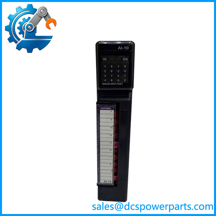
P0924AS
Main Features and Engineering Considerations
RTU Integration
The main engineering characteristic of the is its role within the RTU architecture. It should not be evaluated like a generic PLC I/O card. Its electrical behavior, addressing, field termination, and system configuration depend on the hardware arrangement. Schneider Electric’s documentation specifically places in the I/O-module ordering group.
Legacy System Considerations
The platform is a legacy-generation RTU architecture. That makes configuration records particularly important. A replacement should be matched against the original module designation, hardware revision, cabinet drawings, termination assembly, and channel assignment. Do not substitute an apparently similar analog or digital module solely because the connector or physical dimensions appear compatible.
Avoid Unsupported Signal Assumptions
Some current listings describe as an analog-input module, with one listing claiming eight 4–20 mA inputs. That description is not sufficiently supported by the documentation available for verification.
For a plant maintenance database, it is safer to record as an I/O module until the original Foxboro documentation, module label, or cabinet drawing confirms the exact signal type.
Replacement Testing
Before installing a replacement, document every connected field loop and its termination location. For an analog application, verify loop polarity, signal range, grounding, shield termination, and scaling. For a digital application, verify the expected wet/dry contact arrangement and common reference. The final loop test should be performed from the field device through the and into the RTU application.
Configuration and Software
A physically correct does not necessarily mean that the system will immediately recognize the replacement. Confirm the configuration, module address/position, database assignment, channel scaling, alarm limits, and RTU application configuration before returning the system to service.
Application Scenarios
- Foxboro remote terminal units
- Legacy process monitoring systems
- Remote plant instrumentation
- Utility and infrastructure RTU installations
- Process signal acquisition
- Remote alarm and status monitoring
- Legacy industrial control cabinets
- maintenance and replacement projects
Engineer’s Guide: Field Pitfalls
1. Do not confuse with Foxboro FBM hardware.
belongs to the RTU hardware family. It is not an FBM200/FBM230/FBM2xx fieldbus module.
2. Do not assume the signal type from reseller descriptions.
Available listings conflict. Confirm the actual module function from the original documentation or cabinet records before connecting field wiring.
3. Verify the complete configuration.
The backplane, module position, termination arrangement, and RTU configuration all matter.
4. Preserve the existing channel database.
Record channel assignments, scaling, alarm thresholds, engineering units, and signal conditioning before replacing the module.
5. Inspect the field termination.
A replacement module can be electrically correct but still fail commissioning if the associated terminal assembly or wiring arrangement does not match.
6. Check revision compatibility.
Legacy RTU modules may have hardware revisions that are not interchangeable in every system configuration. Record the revision printed on the existing unit.
7. Test the complete loop.
Do not stop after confirming that the replacement module powers up. Verify the field signal, RTU value, scaling, alarm response, and communications path.
Frequently Asked Questions
What is Foxboro ?
is an I/O module belonging to the Foxboro RTU platform. Schneider Electric’s documentation lists it within the platform’s I/O-module ordering group.
Is an FBM module?
No. is associated with the RTU architecture. It should not be classified as a conventional Foxboro I/A Series FBM.
Is an analog input module?
Some third-party listings describe it as an analog-input module, but the available authoritative material reviewed here does not provide enough detail to verify the exact channel function. For engineering documentation, the safer designation is until the original hardware documentation confirms the signal type.
How many channels does have?
I would not publish a definitive channel count without the applicable hardware documentation. Current secondary listings provide conflicting or insufficient information.
Can be replaced by another I/O module?
Not automatically. The replacement must match the required I/O function, hardware revision, module position, field termination, and configuration.
Is suitable for a new control-system installation?
It is primarily relevant to maintaining an existing installation. For a new system, the engineering basis should be evaluated against the currently supported control/RTU architecture rather than assuming that a legacy module is an appropriate new-design component.
Procurement Note
For purchasing or spare-parts records, specify:
Foxboro — I/O Module
Before accepting the replacement, request confirmation of the complete part number, hardware revision, exact I/O function, channel configuration, compatibility, and associated termination hardware.
I would specifically avoid purchasing based on a description such as “8-channel 4–20 mA analog input” unless that specification can be confirmed against the original Foxboro documentation or the module’s identification label. The available secondary sources are inconsistent, while Schneider Electric’s documentation only establishes as one of the platform’s I/O modules.