Description
Product Overview
In a combustion system, reliable flame detection must distinguish the target burner flame from background radiation, adjacent flames, and ignition activity. The Fireye 95DSS3-1CEXSS addresses this requirement by combining UV and IR sensing with internal signal processing and flame-switch functions. Its two flame relays can be configured independently to respond to the UV sensor, the IR sensor, or a selected combination of both. Adjustable sensor gain, modulation-frequency selection, and switching thresholds help qualified commissioning personnel tune detection to the actual burner and fuel conditions.
The stainless-steel CEXSS version is intended for installations requiring a flame-proof enclosure and includes a display and keypad for local configuration and status monitoring. Two 4–20 mA outputs provide separate indications associated with the flame relays, while the fault relay signals loss of power or an internal scanner fault. The scanner operates as a detection device within a broader burner-management system; it does not replace the burner management controller, required interlocks, or the complete safety validation process. Before replacement, verify the housing certification, sensor arrangement, burner sighting geometry, cable configuration, output wiring, and programmed flame settings.
Key Technical Specifications
| Parameter | Specification |
|---|---|
| Product model | 95DSS3-1CEXSS |
| Manufacturer | Fireye / Honeywell |
| Product family | InSight II |
| Product type | Integrated UV/IR flame scanner |
| Detection sensors | One UV sensor and one IR sensor |
| UV response range | 295–320 nm |
| IR response range | 700–1,700 nm |
| Power supply | 24 VDC |
| Flame relays | 2 independently configurable relays |
| Fault relay | 1 |
| Analog outputs | 2 × 4–20 mA |
| Analog output function | Configurable flame quality or flame signal indication |
| Communications | Remote communication capability; RS-485 wiring is documented in the product manual |
| Local interface | Integrated alphanumeric VFD display and keypad |
| Housing material | 316 stainless steel |
| Housing protection | IP66, as specified for the CEXSS version |
| Hazardous-area marking | Ex d IIC T6, with certification details subject to the applicable approval documentation |
| Ambient operating temperature | −40°C to +65°C for the CEXSS configuration |
| Approximate dimensions | 339.7 mm long; refer to the model-specific drawing for full dimensions |
| Approximate weight | 9.66 kg |
| Mounting | Threaded mounting flange, ordered separately |
| Cooling / purge air | Clean, dry air; the manual specifies 4 SCFM (113 L/min) under stated conditions, with higher flow potentially required by operating conditions |
Specifications are based on the Fireye Type 95DSS3 InSight II technical bulletin and model-specific product information. Verify the exact certification schedule, wiring, mounting flange, and site temperature limits before installation.
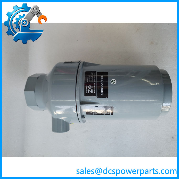
95DSS3-1CEXSS
Major Features and Advantages
1. Dual UV and IR flame detection
The scanner monitors flame radiation in two spectral ranges. This gives commissioning personnel more flexibility when distinguishing the intended flame from background radiation or nearby combustion sources. The two sensors can be assigned to different flame-relay logic configurations rather than being limited to one fixed detection method.
2. Two independently adjustable flame relays
Each flame relay has its own configurable sensing logic, gain, modulation-frequency selection, and switching thresholds. This can support different burner-monitoring requirements within the limits of the approved system design. The actual configuration must be established through documented commissioning tests, not assumed from factory defaults.
3. Separate flame signal outputs
Two 4–20 mA outputs allow flame quality or flame signal information to be sent to compatible monitoring equipment. These signals are useful for diagnostics and trend monitoring, but they should not be treated as substitutes for the scanner’s safety relay contacts.
Wiring warning: The manual specifies internally powered current outputs. Connect them only to compatible passive receiving circuits; do not connect them to an externally powered current loop, which can damage the scanner.
4. Integrated display and keypad
The CEXSS model includes the stainless-steel-version display and keypad for local status viewing and parameter adjustment. This can simplify commissioning and fault investigation when the scanner is installed in an accessible position.
5. Stainless-steel flame-proof housing
The 316 stainless-steel housing is intended for specified hazardous-area applications. Its approval applies only under the conditions, installation practices, cable-entry requirements, and certification markings defined for the particular model. Do not infer suitability for every explosive atmosphere from the housing material alone.
Application Scenarios and Common Pain Points
| Application | Control requirement | Engineering consideration |
|---|---|---|
| Industrial boilers | Verify flame presence during burner operation | Confirm sensor alignment and flame discrimination |
| Industrial furnaces | Monitor flame under changing firing conditions | Tune gain and modulation frequency for the target flame |
| Multi-burner installations | Distinguish the intended flame from neighboring burners | Check field of view and cross-flame response |
| Hazardous-area combustion systems | Flame monitoring within a certified enclosure | Verify area classification and full installation certification |
| Burner maintenance and replacement | Restore the existing flame-detection arrangement | Match the scanner model, settings, mounting, and wiring |
Common field problems
- False flame indication: Investigate background radiation, adjacent burners, sensor alignment, and modulation-frequency settings.
- Flame relay drops out during operation: Check sighting geometry, flame stability, sensor gain, and ON/OFF thresholds.
- No signal at the monitoring system: Verify 24 VDC power, analog output wiring, receiving-circuit compatibility, and the selected signal parameter.
- Fault relay indicates a problem: Check the supply and scanner diagnostic information; do not bypass the fault circuit to maintain burner operation.
- Replacement cannot fit the existing installation: Confirm the CEXSS stainless-steel housing, flange thread, display arrangement, and cable-entry details before ordering.
Related Products
The following Fireye models are useful for evaluating related scanner configurations. They are not automatic substitutes for the 95DSS3-1CEXSS.
| Model | Main distinction |
|---|---|
| 95DSS3-1CEX | InSight II dual UV/IR scanner with flame-proof housing; housing configuration differs from CEXSS |
| 95DSS3-1CEX-2 | Related CEX scanner variant with aluminum housing |
| 95DSS3-1CEX-ND | CEX configuration supplied with a blank cover rather than the integrated display |
| 95DSS3-1WICEX | CEX variant configured for an infrared transmitter interface |
| 95DSS3-1 | Standard InSight II scanner with quick-disconnect cable connections |
| 95DSS3-1WOC | Variant using internal terminal blocks rather than the standard quick-disconnect arrangement |
| 95DSS3-1WINC | Variant intended for retrofit use with specified InSight I cable arrangements |
| 95DISP-1-SS | Display and keypad accessory associated with the stainless-steel scanner configuration |
Confirm the complete part number, housing material, approvals, electrical interface, display arrangement, and mounting dimensions before substituting a related model.
Engineer’s Guide: Three Checks Before Ordering
1. Confirm the hazardous-area requirements. Match the site classification and required approval to the exact 95DSS3-1CEXSS marking and its certification documents. The model’s housing rating does not eliminate the need for correctly certified cable glands, plugs, and installation practices.
2. Verify the existing wiring and mounting. Check the 24 VDC supply, signal wiring, display, mounting flange thread, sight pipe, and purge-air arrangement. Do not assume a different 95DSS3 suffix uses the same cable or terminal arrangement.
3. Preserve and validate the burner settings. Record sensor selection, gain, modulation frequency, relay thresholds, and analog-output configuration before replacement. Have qualified combustion-control personnel perform the required flame-on, flame-off, fault, and shutdown tests after installation.
Critical safety warning: Never bypass flame supervision, fault relay contacts, or burner-management interlocks to keep equipment running. Installation, configuration, and functional testing must follow the manufacturer’s instructions and the site’s applicable combustion-safety procedures.
 dsfgmbh.de+1
Frequently Asked Questions
1. What is the Fireye 95DSS3-1CEXSS used for?
It detects and discriminates burner flames using UV and IR sensors. It is used as part of industrial burner-management and combustion-safety systems.
2. What power supply does it require?
The scanner requires 24 VDC. Do not substitute 24 VAC or connect it to a different supply without explicit manufacturer documentation.
3. What does the CEXSS suffix mean?
It identifies the stainless-steel flame-proof housing configuration. This model includes the 95DISP-1-SS display and keypad and has model-specific hazardous-area certification requirements.
4. Does it provide a 4–20 mA output?
Yes. It provides two 4–20 mA outputs associated with the two flame-relay channels. The output can be configured for flame quality or flame signal indication.
5. Can the 95DSS3-1CEXSS replace another 95DSS3 model?
Not without a compatibility review. Housing material, certification, cable arrangement, operator interface, mounting flange, and application settings can differ among variants.
6. What should be checked before purchasing a replacement?
Confirm the full part number, housing and certification markings, display inclusion, mounting hardware, cable interfaces, condition, and available functional-test evidence. Also confirm warranty terms and delivery lead time.
7. Can this scanner alone guarantee safe burner operation?
No. It is a flame-detection component within a burner-management system. Safe operation also depends on the approved control architecture, interlocks, wiring, commissioning, and complete system testing.