Description
Product Overview
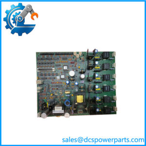
When a legacy industrial drive develops a control fault, replacing the main control card requires more than matching the board’s outline and connectors. The GE DS200SDCCG1AFD is a Drive Control Card used in compatible GE Mark V drive and exciter architectures. It contains processing circuitry and interfaces that coordinate drive-control operations and exchange signals with other boards. Its role makes exact part-number identification, revision verification, and preservation of the original configuration important during maintenance.
The GE DS200SDCCG1AFD uses three microprocessors and dual-ported RAM to support its control and data-processing functions. Its board group is associated with AC2000, DC2000, and EX2000 applications. Hardware jumpers and software parameters can affect operation, and the DS200 version must not be confused with DS215SDCC variants that include onboard software memory devices. Before installing a replacement, compare the full catalog number, inspect the installed configuration, and follow the applicable GEI-100029 procedures.
Key Technical Specifications
| Parameter | Specification |
|---|---|
| Product Model | DS200SDCCG1AFD |
| Manufacturer | General Electric |
| Control Platform | Mark V / DS200 |
| Functional Acronym | SDCC |
| Product Type | Drive Control Card |
| Board Group | G1A |
| Functional Revision | A / F |
| Artwork Revision | D |
| Processor Architecture | Three microprocessors |
| Shared Memory | Dual-ported RAM |
| Configuration Method | Hardware jumpers and software parameters |
| Diagnostic Indicators | 10 LEDs reported for this board variant |
| Supported Application Groups | AC2000, DC2000, EX2000 |
| Reference Manual | GEI-100029 |
| Supply Voltage | Verify from the applicable system documentation; do not infer from the part number alone |
| Communication Interfaces | Board-to-board interfaces; exact connected interfaces depend on the installed system configuration |
| Operating Temperature | Verify against the applicable GE documentation |
| Installation | Compatible GE Mark V drive control rack |
Specification note: Publicly available material does not establish every electrical and environmental rating for this exact revision. Confirm those details against the original manual and the drive cabinet’s documentation before commissioning.
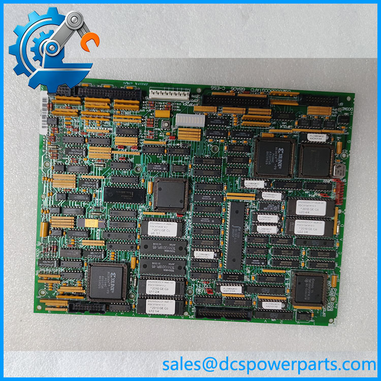
DS200SDCCG1AFD
Major Features and Advantages
Multi-processor control architecture
The DS200SDCCG1AFD contains three microprocessors and dual-ported RAM. This architecture supports coordinated processing of drive-control tasks and shared data. The board operates as part of a larger control system; its exact functions depend on the application software and connected hardware.
Drive and exciter interface processing
The SDCC board provides core processing and interface functions for compatible drive and exciter applications. It exchanges signals with other boards to support control operations and the processing of motor, drive, and customer I/O signals. Confirm the target equipment and application group before selecting a replacement.
Configurable hardware and software
Jumpers and software parameters affect board configuration. During maintenance, record the original jumper positions and preserve the existing application settings where the documented procedure requires it. Do not copy jumper settings from a different SDCC revision or application group without checking the manual.
Diagnostic LED indicators
The board has 10 diagnostic LEDs according to available product documentation. These indicators can help technicians identify startup or operating faults, but the indicated state must be interpreted using the applicable diagnostic tables. A successful power-up does not by itself prove correct drive operation.
Application-specific board grouping
The G1A group is associated with AC2000, DC2000, and EX2000 applications. Other SDCC groups may serve different equipment families or use different firmware and parameter arrangements. This distinction is important when sourcing a replacement for a production-critical system.
Maintenance of legacy control systems
A verified replacement can help maintain an existing Mark V drive installation without requiring an immediate redesign of the control architecture. The main procurement risks are incorrect revision selection, missing configuration information, damaged connectors, and insufficient functional testing.
Application Scenarios and Common Pain Points
- AC drive systems: Control processing within compatible AC2000 drive applications.
- DC drive systems: Control-board replacement in supported DC2000 applications.
- Excitation systems: Maintenance of compatible EX2000 excitation equipment.
- Industrial plant maintenance: Replacement of a failed or suspect SDCC board where the original Mark V architecture remains in service.
Common field issues include:
- Drive fails to start: Check board status, power supply, system fault records, configuration, and the connected control circuitry.
- Unexpected control behavior after replacement: Verify the board group, revision, jumper positions, and software parameters.
- Diagnostic LEDs indicate a fault: Use the correct diagnostic table and investigate related boards and system signals before replacing additional components.
- Replacement board powers up but the drive remains unavailable: Check configuration and interface compatibility, not just the board’s power-on condition.
- Uncertainty about onboard software: Confirm whether the required memory devices and software configuration are present. The DS200SDCC and DS215SDCC families differ in their documented onboard software memory arrangements.
Related Products
| Model | Product type / distinction |
|---|---|
| DS200SDCCG1A | Base G1A Drive Control Card designation |
| DS200SDCCG1ABA | G1A SDCC revision variant |
| DS200SDCCG1ACA | G1A SDCC revision variant |
| DS200SDCCG1AGD | G1A SDCC revision variant |
| DS200SDCCG1AHD | G1A SDCC revision variant |
| DS200SDCCG3A | SDCC group associated with DC1000 applications |
| DS200SDCCG4A | SDCC group associated with TC2000 rack applications |
| DS215SDCCG1 | SDCC family variant with onboard software memory |
| DS200LDCCH1A | Mark V drive control board in a different functional family |
| DS200DCFBG1B | Drive control power supply board family |
These are related Mark V or drive-control components, not guaranteed drop-in replacements. Confirm the exact assembly number, revision, firmware, and intended application before substitution.
Engineer’s Guide: Three Checks Before Ordering
1. Match the full part number. Confirm DS200SDCCG1AFD, including all suffix characters and revision markings. Do not purchase solely by the SDCC designation.
2. Verify application and configuration. Establish whether the installed system is AC2000, DC2000, or EX2000. Record the original jumper positions and determine whether software parameters or memory devices must be transferred or restored according to the manual.
3. Require meaningful functional-test evidence. Ask the supplier to document inspection of the board, connector condition, diagnostic behavior, and the scope of any functional testing. A visual inspection or LED check alone does not establish operational compatibility.
Safety warning: Isolate power to the drive, verify that hazardous voltage is absent, and follow the manufacturer’s discharge and electrostatic-discharge precautions before handling the board. Do not remove or insert the card while the system is powered unless the applicable documentation explicitly permits it.
Frequently Asked Questions
1. What is the GE DS200SDCCG1AFD used for?
It is a Mark V SDCC Drive Control Card that provides processing and interface functions in compatible drive and exciter systems. Its application depends on the G1A board group and the installed system configuration.
2. Which applications use the ?
The G1A group is documented for AC2000, DC2000, and EX2000 applications. Confirm the equipment model and original board details before ordering.
3. How many processors does the have?
Available technical documentation identifies three microprocessors and dual-ported RAM. These components support the board’s control-processing and shared-data functions.
4. Can the be replaced by another DS200SDCCG1A variant?
Not automatically. Revision differences, application requirements, firmware, jumper configuration, and board population must be checked. Verify the proposed replacement against GEI-100029 and the installed drive documentation.
5. What is the difference between DS200SDCC and DS215SDCC?
The referenced GE manual states that the DS215SDCC includes five onboard software memory devices, while the corresponding sockets on the DS200SDCC are empty. Replacement planning must account for the software and configuration requirements of the specific installation.
6. What should be checked if the board powers up but the drive does not operate correctly?
Review diagnostic indications, application compatibility, jumper settings, software parameters, and communication with associated boards. Confirm the fault using the system’s diagnostic procedures before attributing the problem solely to the replacement board.
7. What information should buyers provide when requesting a replacement?
Provide the complete part number, clear photos of the label and revision markings, the drive or exciter model, the original board’s configuration details, and the required condition. Request warranty terms, dispatch lead time, and test documentation appropriate to the intended application.
Procurement recommendation: For the GE , prioritize exact revision matching, application-group verification, and documented functional testing. In a legacy drive system, these checks are more meaningful than connector fit or visual similarity alone.