Description
GE DS200QTBAG1ADC QTBA RST Termination Board
Product Introduction
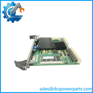
The GE DS200QTBAG1ADC is a QTBA RST Termination Board used in the GE Mark V Speedtronic turbine control system. Its primary function is to provide the field-side termination and signal-routing interface between the R/S/T control cores and connected turbine instrumentation and actuators. It should therefore be treated as a termination and interface assembly, not as a standalone PLC CPU or conventional analog input module. The board is documented for use in R, S, and T cores at location 6, where it forms part of the signal path associated with turbine control functions.
The GE DS200QTBAG1ADC contains two terminal blocks, each providing 72 signal-wire terminals. The board also includes a 40-pin JFF connector and a serial connector. Documented signal functions include six magnetic pulse-rate inputs, eight servo-value outputs, and six excitation sources for LVDT devices. A single J1 jumper modifies input signal selection, with the documented default position being 20 mA. These features make the board particularly relevant to Mark V turbine applications involving speed/pulse measurement, servo control, and LVDT-based position feedback.
For replacement work, the complete GE DS200QTBAG1ADC identifier matters. The ADC suffix represents a specific revision configuration, so a visually similar QTBA board should not be assumed interchangeable. Before installation, compare the terminal wiring, JFF connection, serial connection, J1 jumper position, core location, and associated Mark V control boards with the existing cabinet documentation. This is especially important when the replacement is being installed in an operating turbine control system.
Technical Specifications
| Parameter | Specification |
|---|---|
| Product Model | DS200QTBAG1ADC |
| Manufacturer | General Electric (GE) |
| Product Series | Mark V / DS200 Speedtronic |
| Functional Acronym | QTBA |
| Product Type | RST Termination Board |
| Primary Function | Signal termination and routing |
| Typical Installation | R, S, T cores, location 6 |
| Terminal Blocks | 2 |
| Signal Terminals | 72 per block |
| 40-Pin Connector | 1 × JFF |
| Serial Connector | 1 |
| Magnetic Pulse-Rate Inputs | 6 |
| Servo-Value Outputs | 8 |
| LVDT Excitation Sources | 6 |
| Configuration Jumper | J1 |
| Documented J1 Default | 20 mA position |
| Revision | ADC |
| Assembly Type | Normal assembly |
| PCB Coating | Normal coating |
| Communication | Serial interface documented; no standalone Ethernet function established |
| Working Voltage | Application-dependent; not reliably established from available exact-model records |
| Operating Temperature | Not reliably established for the bare board |
| Protection Rating | Not independently established |
| Operating Accuracy | Not applicable as a standalone measurement instrument |
The six pulse-rate inputs, eight servo outputs, six LVDT excitation sources, 72-terminal blocks, JFF connector, serial connector, and J1 configuration are consistently reported for this exact part number.
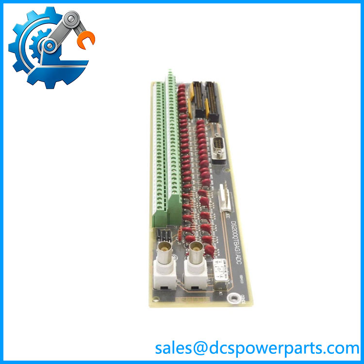
DS200QTBAG1ADC
Main Features and Engineering Considerations
RST Termination Architecture
The DS200QTBAG1ADC belongs to the RST termination architecture of the Mark V system. Its purpose is to organize signals between the control cores and field-connected equipment. The board should therefore be evaluated as part of the complete Mark V signal chain rather than independently.
High-Density Field Wiring
Two terminal blocks with 72 signal-wire positions each provide a substantial field interface. During replacement, terminal identification is more important than simply matching the PCB outline. Wire tags, terminal numbers, connector locations, and cabinet drawings should be cross-checked before disconnecting the original unit.
Pulse-Rate Inputs
Six magnetic pulse-rate inputs are documented for the board. These inputs are relevant to turbine speed and other pulse-based measurement circuits. The exact signal assignment depends on the Mark V application, so the six inputs should not automatically be described as six identical speed channels.
Servo-Value Outputs
Eight servo-value outputs are associated with the board. These circuits can form part of turbine actuator control, but the actual field function should be confirmed against the specific cabinet drawing rather than inferred solely from the presence of a servo output.
LVDT Excitation
Six LVDT excitation sources are documented. This is significant for systems using LVDT-based valve or actuator position feedback. The excitation circuitry and associated feedback path should be checked together when diagnosing a position-control problem.
J1 Jumper Configuration
The J1 jumper modifies input-signal selection, with 20 mA documented as the default position. This makes jumper verification part of a proper replacement procedure. Do not assume that the factory/default jumper position is necessarily the correct position for every installed cabinet.
Revision Control
The requested board is . The ADC suffix should be retained in procurement records. Other QTBA boards may have different hardware or artwork configurations even if their base functional designation looks similar.
Application Scenarios
- GE Mark V gas turbine control systems
- GE Mark V steam turbine control systems
- R/S/T turbine control cores
- Turbine fuel-flow signal interfaces
- Magnetic pulse-rate measurement
- Servo-valve control circuits
- LVDT excitation and position-feedback systems
- Mark V turbine-control cabinet refurbishment
- Legacy turbine-control spare-board programs
Engineer’s Guide: Field Pitfalls
1. Do not confuse QTBA with TCQA or TBQC.
QTBA is a termination board. TCQA and other Mark V boards perform different signal-processing or interface functions.
2. Preserve the complete part number.
Use , not simply “QTBA,” when purchasing a replacement.
3. Check J1 before energization.
The documented default is 20 mA, but the installed system’s required signal selection must be confirmed from the cabinet documentation.
4. Verify the R/S/T location.
This board is documented for location 6 in the R, S, and T cores. Physical position and cable routing matter in a Mark V cabinet.
5. Check all 144 field terminals.
Two 72-terminal blocks create a high-density wiring interface. Label wires before removal and verify each terminal against the approved drawing.
6. Do not assume the serial connector is a modern network interface.
The board has a serial connector, but there is no reliable evidence that it provides Ethernet, Modbus TCP, or another modern industrial Ethernet protocol.
7. Verify the LVDT circuit as a complete chain.
An apparent LVDT problem can originate in excitation, transducer wiring, termination, the associated control board, or the feedback circuit. Replacing the QTBA alone does not establish the fault location.
8. Be cautious with online specifications.
Some listings add unsupported temperature, voltage, communication, or analog-range specifications. For a turbine-control replacement, cabinet documentation should take precedence over generic reseller specifications.
Frequently Asked Questions
What is GE ?
It is a GE Mark V QTBA RST Termination Board used to terminate and route signals within the R/S/T turbine-control architecture.
How many terminals does have?
It has two terminal blocks with 72 signal-wire terminals per block, for 144 documented terminal positions.
What are the main signal functions?
The board is documented with six magnetic pulse-rate inputs, eight servo-value outputs, and six LVDT excitation sources.
What is the JFF connector?
JFF is the documented 40-pin connector on the QTBA board. It forms part of the board’s internal Mark V signal interface.
What does the J1 jumper do?
J1 modifies input-signal selection. The documented default position is 20 mA. The actual position on a replacement should match the required cabinet configuration.
Is an analog input module?
It is more accurately described as an RST termination board. Although it handles analog-related and pulse/servo/LVDT signal paths, it should not be represented as a self-contained modern analog I/O module.
Does it have Ethernet?
No standalone Ethernet function has been reliably established for this exact board. A serial connector is documented, but that should not be represented as Ethernet or Modbus without system-specific documentation.
What should be checked before ordering?
Confirm the full part number, revision, R/S/T core location, terminal assignments, JFF and serial connections, J1 jumper position, and the connected pulse, servo, and LVDT circuits.
Procurement Note
For a critical Mark V replacement, request clear photographs of the complete board label, ADC revision marking, two terminal blocks, JFF connector, serial connector, and J1 jumper. The physical board should be compared against the installed unit before shipping.
For refurbished inventory, inspect terminal hardware and connector condition, verify jumper configuration, check for corrosion or heat damage, and perform appropriate continuity/functional testing against the intended Mark V configuration. Avoid accepting unsupported claims about universal supply voltage, temperature rating, accuracy, or modern network protocols when those values are not confirmed by the turbine documentation.