Description
Key Technical Specifications
| Parameter | Specification |
|---|---|
| Product Model | 7DI140.70 |
| Manufacturer | B&R Industrial Automation |
| Product Family | System 2003 |
| Product Type | Digital Input Module |
| Number of Inputs | 10 |
| Rated Input Voltage | 24 VDC |
| Input Voltage Range | 18–30 VDC |
| Input Configuration | Sink |
| Input Threshold | <5 VDC Low / >15 VDC High |
| Input Current | Approx. 8 mA at 24 VDC |
| Input Frequency | Up to 50 kHz |
| High-Speed Inputs | 4 inputs |
| Event Counter Inputs | 2 inputs |
| Encoder Function | Direction-dependent position detection / incremental encoder |
| Counter Size | Up to 32-bit for encoder operation |
| Encoder Evaluation | 4-fold |
| Signal Form | Square-wave pulse |
| Channel-to-Channel Isolation | No |
| Channel-to-PLC Isolation | Yes |
| Power Consumption | Max. 0.4 W |
| Protection Rating | IP20 |
| Operating Temperature | 0–60°C horizontal; 0–50°C vertical |
| Storage Temperature | -25–70°C |
| Relative Humidity | 5–95%, non-condensing |
| Mounting | B&R 2003 screw-in module |
| Interface | AF101 adapter / CPU / Power Panel interface |
| Required Terminal Block | TB712.9 or TB712.91 |
B&R identifies the 7DI140.70 as a ten-input, 24 VDC sink digital input module. Its documented special functions include two event-counter or position-detection inputs and four inputs usable for high-speed functions.
The historical System 2003 documentation gives an important electrical detail: the input range is 18–30 VDC, with switching thresholds below 5 VDC and above 15 VDC. The module consumes a maximum of 0.4 W.
Application Scenarios & Pain Points
A standard digital input may be perfectly adequate for a proximity switch that changes state once every few seconds. It is a different story when the same cabinet is expected to capture encoder pulses or high-frequency events without losing edges.
- Incremental encoder feedback: Inputs can be configured for direction-dependent position detection, with documented 50 kHz input frequency and fourfold evaluation.
- Event counting: Two inputs support event-counter operation. This suits applications where pulse accumulation matters more than ordinary ON/OFF status.
- High-speed machine functions: Four inputs can be used for high-speed functions such as gate timing and frequency measurement, subject to the CPU-interface configuration.
- General 24 VDC field signals: The remaining inputs can handle conventional industrial digital signals from switches, sensors, and machine devices.
Field note: The input channels are not channel-to-channel isolated. If the field devices have different ground potentials, noise, or long cable runs, check the grounding arrangement before assuming the input card is at fault.
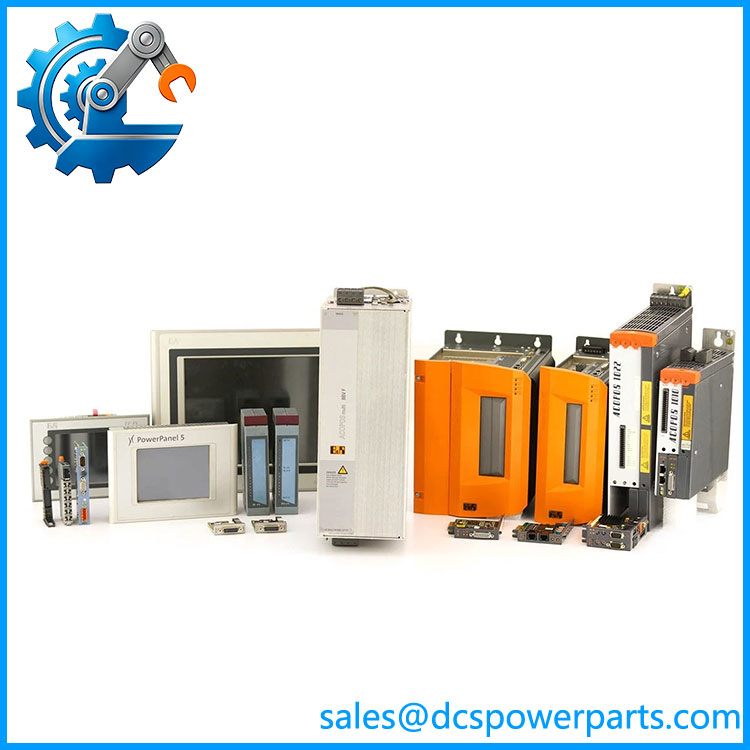
7DI140.70
Related Products
- B&R 7DI138.70 — Ten-channel 24 VDC sink input module from the same System 2003 family, but its documented input frequency is 20 kHz. It is worth considering for ordinary high-speed digital acquisition where the specialized DI140 functions are not required.
- B&R 7DI135.70 — Four-channel 24 VDC sink input module with incremental-encoder operation up to 50 kHz, event-counter operation up to 100 kHz, and a 24 VDC comparator output. Its channel count and functions differ substantially from the 7DI140.70.
- B&R 7DO135.70 — Four-channel FET digital output module for 12–24 VDC loads. It complements the 7DI140.70 when the control cabinet requires both high-speed inputs and semiconductor outputs.
- B&R 7DO138.70 — Eight-channel 24 VDC digital output module rated at 0.5 A per output. It provides output capability rather than input acquisition and is useful for actuator-side expansion.
- B&R 7AI261.7 — Specialized one-channel 24-bit strain-gauge input module. It belongs to the same broader B&R 2003 screw-in module ecosystem but is intended for load cells and bridge measurements rather than discrete signals.
- B&R 7IF311.7 — System 2003 interface module with an RS232 interface. It can support serial communication requirements in cabinets that also contain 7DI140.70 modules.
- B&R 7TB712.9 — Twelve-pin screw-clamp terminal block for the System 2003 module. It is an installation accessory rather than an alternative I/O card and must be ordered separately.
- B&R 7TB712.91 — Twelve-pin cage-clamp version of the required terminal block. Choose it when the existing cabinet uses spring/cage-clamp field termination.
The Engineer’s Guide: Field Pitfalls to Avoid
⚠️ Do not assume every 24 VDC input channel has the same high-speed capability.
The DI140 has ten inputs, but its special functions are assigned to particular inputs. Two support event-counter or position functions, while four can be used for high-speed functions through the CPU interface. Review the original channel assignment before rewiring.
⚠️ Do not overlook the sink-input configuration.
This module is specified for 24 VDC sink inputs. Verify how the existing sensors switch the circuit before replacing it with a module having a different input architecture.
⚠️ Do not treat the module as channel-to-channel isolated.
The documentation indicates isolation between the input side and PLC, but not between individual input channels. Shared field references can therefore matter, especially with distributed sensors and long cable runs.
Practical check: Record the original input number, sensor type, signal voltage, encoder A/B assignment, counter configuration, and CPU interface arrangement. Then verify each channel with a real field signal after installation—not merely by checking the input LED.
Frequently Asked Questions (FAQ)
What is B&R 7DI140.70 used for?
The 7DI140.70 is a System 2003 digital input module with 10 × 24 VDC sink inputs. It is designed for both conventional digital signals and higher-speed applications involving event counting, encoder position detection, gate timing, and frequency measurement.
How many inputs does 7DI140.70 have?
It has 10 digital inputs. Two inputs provide event-counter or direction-dependent position functions, and four inputs can be used as high-speed inputs through the CPU interface.
What is the maximum input frequency of 7DI140.70?
The documented input frequency is 50 kHz. In encoder operation, the module supports fourfold evaluation, so the resulting calculated count frequency can be higher than the basic signal frequency.
Can 7DI140.70 be used with an incremental encoder?
Yes, within the documented configuration. The System 2003 documentation identifies encoder operation with direction-dependent position detection and fourfold evaluation. The applicable inputs and wiring must be configured correctly before commissioning.
Is the TB712 terminal block included with 7DI140.70?
No. B&R explicitly identifies the TB712 terminal block as a separately ordered accessory. Available choices include 7TB712.9 with screw terminals and 7TB712.91 with cage-clamp terminals.
Can 7DI140.70 directly replace 7DI138.70?
Mechanically related, but do not assume functional equivalence. Both are ten-input 24 VDC sink modules, yet the DI140 provides specialized event-counter, encoder, and high-speed functions that distinguish it from the DI138. If the existing application uses those functions, replacing it with another ten-channel input module may remove required capabilities.