Description
Key Technical Specifications
| Parameter | Specification |
|---|---|
| Manufacturer | B&R |
| Model | 2PS740.9 |
| Module designation | PS740 |
| Product family | System 2010 |
| Product type | AC power supply module |
| Nominal input voltage | 100–240 VAC |
| Permitted input range | 90–270 VAC |
| Input frequency | 47–63 Hz |
| Rated output power | 100 W |
| Secondary output | 24 VDC (confirm against the applicable output characteristic diagram) |
| Maximum input current requirement | 1.1 A |
| Input fuse | 1.6 A, slow-blow, 250 V |
| Overvoltage withstand | 750 V peak, 1.3 ms non-periodic |
| Thermal protection | Internal housing-temperature monitoring |
| Current/power protection | Output power monitoring and current limitation |
| Status indication | LED indicators |
| READY relay | Normally open contact |
| READY relay contact rating | 2 A; nominal switching voltage 24 VDC / 230 VAC |
| Compatible base plates | BP200, BP201, BP210 |
| Dimensions (H × W × D) | 285 × 40 × 185 mm |
| Certification | C-UL-US listed in the referenced hardware manual |
The manufacturer identifies 2PS740.9 as a 100–240 VAC, 100 W power supply for the B&R 2010 system. The output power varies with input voltage and internal operating temperature; consult the original output characteristic diagram when calculating the available load capacity.
Product Introduction
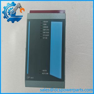
The B&R 2PS740.9 is an AC power supply module designed for the B&R System 2010 automation platform. Identified by the module designation PS740, it accepts a nominal 100–240 VAC input and provides up to 100 W of power for the controller system’s secondary supply.
The module includes LED status indication, a READY relay, thermal monitoring, and output power limitation. These functions help maintenance personnel identify supply faults and protect the rack against excessive load or elevated internal temperature.
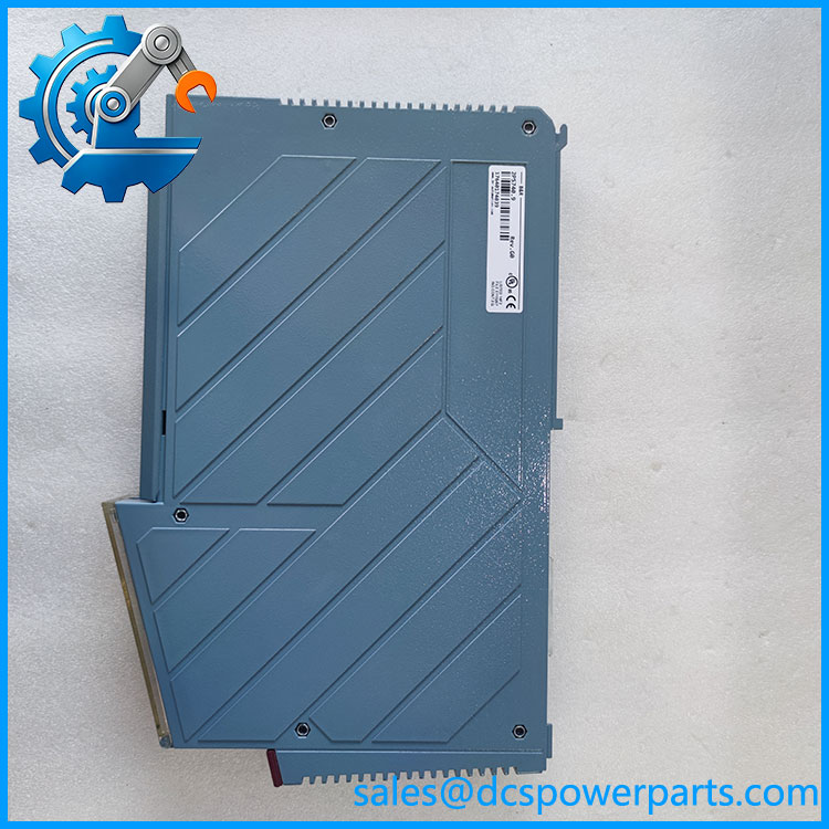
2PS740.9
Application Scenarios & Field Pitfalls (Engineer’s Perspective)
A System 2010 rack may experience intermittent resets, abnormal module behavior, or power-status alarms when its supply is overloaded or operating outside its specified input conditions. Before replacing the 2PS740.9, check the incoming AC supply, rack loading, ventilation, and the condition of the associated base plate.
Typical application scenarios include:
- PLC control cabinets: Supplying the secondary power required by B&R System 2010 controller hardware.
- Manufacturing equipment: Maintaining power to installed System 2010 automation racks.
- Process-control installations: Supporting legacy PLC systems where the original power architecture remains in service.
- Industrial maintenance: Replacing a failed PS740 module while retaining the existing base plate and I/O arrangement.
Field pitfalls
1. Check input voltage and frequency. The nominal input range is 100–240 VAC, with a documented permissible range of 90–270 VAC at 47–63 Hz. Measure the supply under operating conditions. Do not assume that an unloaded voltage measurement identifies intermittent supply problems.
B&R: Perfection in Automation+1
2. Calculate the actual rack load. The 100 W rating is not necessarily available under every input-voltage and temperature condition. B&R documentation states that available output power decreases as input voltage falls or internal temperature rises. Check the original output-power curve and account for the combined load of the installed modules.
Manuals+
3. Inspect the READY relay and protection circuit. The READY contact is normally open and has a documented maximum contact load of 2 A. Check the associated wiring and external protection before interpreting a relay-status problem as an internal PSU failure. Never replace the internal fuse with a higher-rated fuse; the documented rating is 1.6 A slow-blow, 250 V.
For incoming inspection, verify the PS740 designation, complete 2PS740.9 part number, enclosure condition, connectors, and status LEDs. A suitable functional test should include startup, output voltage under load, thermal behavior, and READY relay operation.
Related Products
The following parts are documented within the B&R System 2010 hardware family:
- 2PS425.9 (PS425) — 100 W DC-input power supply module. Accepts 24 VDC nominal input rather than the AC input used by the 2PS740.9.
- 2BP200.4 (BP200) — System 2010 base plate with one I/O module slot.
- 2BP201.4 (BP201) — System 2010 base plate with four I/O module slots.
- 2BP210.4 (BP210) — System 2010 base plate with one I/O module slot and I/O bus termination.
- 2BP202.4 (BP202) — Expansion base plate for remote I/O or I/O bus expansion.
- 2BP300.4 (BP300) — Two-slot CPU base plate with system bus termination.
- 2CP100.60-1 — B&R System 2010 CPU module with serial communication interfaces.
- 2CP104.60-1 — System 2010 CPU module variant with its own hardware configuration.
- 2EX301.5 — I/O bus expansion slave module.
- 2EX302.5 — I/O bus expansion master module.
These are related System 2010 components, not direct replacements for the PS740 power supply. Confirm the rack configuration and power requirements before selecting alternatives.
Procurement and quality-control note: Specify the complete part number 2PS740.9 and module designation PS740. Confirm that the required input is 100–240 VAC rather than the 24 VDC input supported by the 2PS425.9. Before installation, inspect the AC input terminals, output connections, fuse compartment, and READY relay. For surplus units, request a loaded output test and verification of the READY relay and thermal protection.