Description
Key Technical Specifications
| Parameter | Specification |
|---|---|
| Manufacturer | Bosch Rexroth Indramat |
| Model | TVM2.4-050-220/300-W1 |
| Product Category | Servo drive power supply |
| Series | TVM 2.4 |
| Type Current | 50 A |
| Main Input Voltage | 3-phase, 220 VAC |
| Input Frequency | 50–60 Hz |
| Nominal DC Bus Voltage | 300 VDC |
| Continuous DC Bus Power | 7.5 kW |
| Peak DC Bus Power | 60 kW for 0.3 seconds |
| Cooling Method | Built-in blower |
| Mounting | Vertical installation |
| Protection Rating | IP10 |
| Dimensions | Approximately 105 × 390 × 355 mm |
| Weight | Approximately 15 kg |
| Control-Electronics Voltage | Depends on final type-code suffix |
The 7.5 kW continuous and 60 kW peak ratings are published for the TVM 2.4 configuration. Actual available power depends on the connected drive modules, operating duty, cooling conditions, and cabinet installation.
Product Introduction
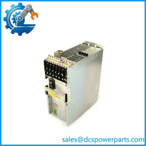
The Bosch Rexroth Indramat TVM2.4-050-220/300-W1 is a central power supply module for legacy modular AC servo drive systems. It accepts three-phase 220 VAC input and supplies a nominal 300 VDC link for compatible downstream drive modules. Its integrated blower supports thermal management during continuous operation.
The TVM module is a power-supply component, not an individual axis servo amplifier. Correct selection requires matching the complete type code, control-electronics voltage, connected drive modules, and cabinet power arrangement.
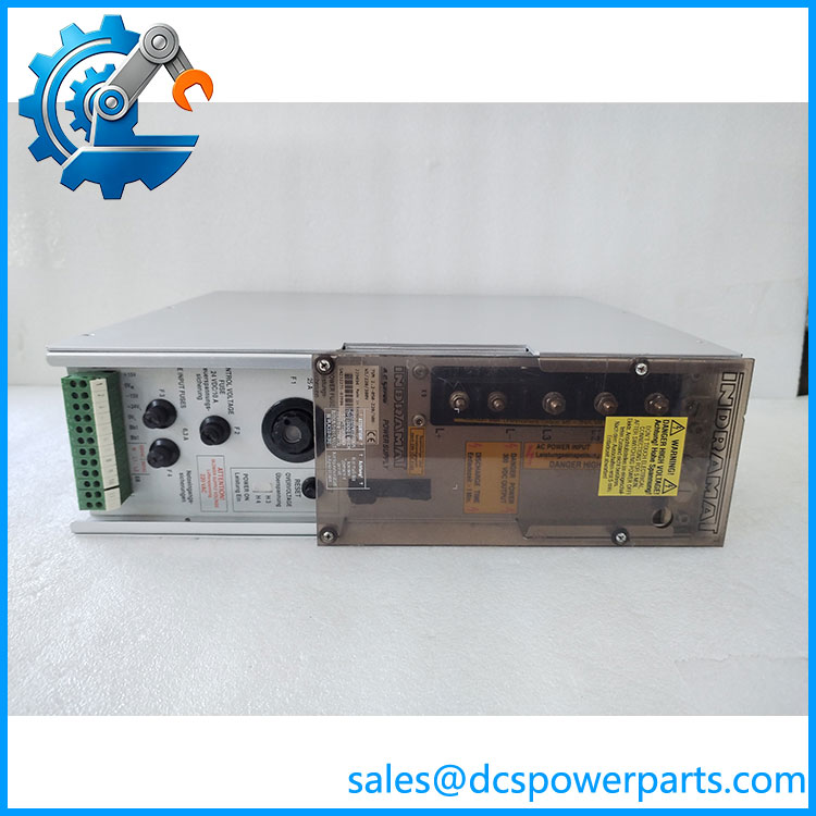
TVM2.4-050-220300-W1
Application Scenarios & Field Pitfalls
Typical applications
- CNC machine tools: Supplies the DC link for compatible servo amplifiers controlling feed axes and machine motion.
- Industrial machine drives: Provides shared DC-bus power for multiple drive modules in a centralized cabinet.
- Legacy SERCOS drive systems: Supports compatible Indramat drive architectures using modular power and axis units.
- Machine-tool maintenance: Replaces a failed central supply module where the existing drive configuration remains in service.
Field checks before replacement
- Match the full suffix. The
/115/220and/220/380versions have different control-electronics supply arrangements. They must not be treated as identical. - Check incoming power. Confirm three-phase supply voltage, frequency, protective devices, and cabinet transformer arrangement.
- Calculate DC-bus loading. Verify the combined continuous and peak requirements of all connected drive modules.
- Inspect regeneration and braking hardware. Confirm whether the system uses an external bleeder module, capacitor module, braking contactor, or resistor. The TVM power supply should not be assumed to include every braking component.
- Check cooling. Inspect the internal blower, air passages, cabinet ventilation, and dust accumulation. A functioning power stage can still trip under thermal load if airflow is restricted.
- Follow DC-bus discharge procedures. The 300 VDC link presents a hazardous stored-energy condition. Isolate the supply and verify discharge with an appropriate meter before handling connections.
Related Products
These components belong to the Indramat TVM drive-power architecture. Their functions differ, so they are not automatic substitutes.
- TVM2.2-050-220/300-W1/115/220 – Related TVM 2.2 supply configuration.
- TVM2.4-050-220/300-W1/115/220 – TVM 2.4 version with the specified 115/220 control-electronics voltage suffix.
- TVM2.4-050-220/300-W1/220/380 – TVM 2.4 version with a different control-electronics voltage arrangement.
- TBM1.2-40-W1-024 – Additional bleeder module.
- TCM1.1-04-W0 – Additional capacitor module, 4 mF.
- TCM1.1-08-W0 – Additional capacitor module, 8 mF.
- CZ1.02 – Additional 2 mF capacitor.
The TVM 2.4 manual identifies these as available configurations or accessories. Selection depends on the original cabinet design and connected drive load.
Procurement and Replacement Notes
Before purchasing, request a clear photograph of the complete nameplate. The submitted designation, TVM2.4-050-220300-W1, does not show the final control-electronics voltage suffix. Do not assume that a listing with a similar base number is electrically interchangeable.
For replacement evaluation, verify:
- Complete type code and manufacturer material number
- 50 A rating and 220 VAC three-phase input
- 300 VDC bus compatibility
- Control-electronics voltage suffix
- Blower condition and cooling performance
- Bleeder, capacitor, and braking-system configuration
- Terminal condition and documented load testing
Important: The complete suffix is essential for a reliable replacement match. If you provide the nameplate photograph or full material number, the exact configuration can be narrowed down.