Description
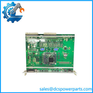
Alstom SPU232.2 029.366 817
Product Introduction
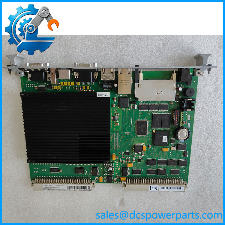
In an excitation or static-frequency-converter cabinet, the processor board is not just another replaceable PCB. It sits at the control layer where excitation regulation, converter sequencing, reference handling, and speed-control functions are coordinated. Alstom SPU232.2 029.366 817 is identified in technical documentation as an SPU232 processor board used for these control functions, alongside the ICP232 for converter-near current control and pulse generation.
The SPU232.2 also appears in documentation for the Semipol D3.1 automatic excitation regulator and static-frequency-converter architecture. Available technical listings identify the board as a Single Processor Unit with VMEbus A32/D32, while one documented configuration specifies an AMD Geode LX800 processor and Ethernet interfaces. Those detailed hardware characteristics should be treated as configuration-specific until the physical revision is checked.
Key Technical Specifications
| Parameter | Specification |
|---|---|
| Product Model | SPU232.2 |
| OEM Part Number | 029.366 817 |
| Product Type | Single Processor Unit / processor board |
| System Application | Excitation and static-frequency-converter control |
| Controller Function | Excitation control, SFC control, reference/setpoint functions and speed-control processing |
| Bus | VMEbus |
| VME Interface | A32/D32 |
| Processor | AMD Geode LX800, 500 MHz* |
| Cache | 128 KB L2 cache* |
| RAM | 256 MB* |
| Flash | 128 MB* |
| Dual-Port RAM | 512 KB on VMEbus* |
| Ethernet | ETH1 10/100Base-T; ETH2 10/100/1000Base-T* |
| Graphics | VGA interface reported, up to 1024×768 / 1600×1200 depending configuration* |
| Reported Revision | Rev.16, BIOS V1.2.17* |
| Mounting | VME/rack-based system installation |
| Condition | Verify actual inventory condition |
*The processor, memory, Ethernet and VGA data are reported for the SPU232.2-CAN / Rev.16 configuration in secondary technical documentation. They should not automatically be assumed for every board carrying the 029.366 817 number without checking the physical unit.
Major Features / Advantages
Central Processing for Excitation Control
The is documented as the processor board for the excitation equipment. Its software functions extend beyond basic signal handling: the same controller architecture is used for excitation regulation, static-frequency-converter control, setpoint preprocessing, and speed-control functions. That makes the board a central computing element rather than a conventional I/O module.
SPU232.2 029.366 817
Role in Static-Frequency-Converter Control
The technical documentation gives a useful picture of the division of labor between the and ICP232. The handles the higher-level controller functions, while the ICP232 performs converter-near current control, pulse generation, and time-critical protection functions. This distinction matters during troubleshooting. Replacing the wrong board because both are described as “controller” hardware can send the investigation in the wrong direction.
VME-Based Processing Architecture
The documented .2-CAN configuration uses a VMEbus A32/D32 interface. The reported 512 KB dual-port RAM also indicates that the board is designed to exchange data through the VME architecture rather than functioning as an isolated industrial computer.
Computing Hardware
For the documented Rev.16 configuration, the processor is an AMD Geode LX800 at 500 MHz with 256 MB RAM, 128 MB flash storage and 512 KB dual-port RAM. Ethernet connectivity is also reported, with one 10/100Base-T interface and one 10/100/1000Base-T interface. These figures are useful when identifying a board, but procurement should still compare the actual PCB revision, BIOS information, and installed option set.
Long-Term Legacy-System Value
The practical value of an .2 spare is often tied to maintaining an existing power-generation control system rather than designing a new installation. If the original controller architecture is still operational, retaining a correctly identified processor board can avoid an unnecessary control-system migration during a forced outage.
That does not mean every .2 board is automatically interchangeable. Firmware, BIOS, board revision, application image, peripheral configuration and the associated ICP232/control hardware all need to be considered before commissioning.
Application Scenarios & Pain Points
Excitation-System Maintenance
The .2 is documented as part of an automatic excitation-regulator architecture. Its control software performs excitation-related processing and communicates with the surrounding converter and plant-control structure.
Static-Frequency-Converter Systems
Technical documentation specifically identifies .2 029.366 817 as an alternative processor board for the static-frequency-converter control system. The handles the higher-level control functions while the ICP232 handles converter-near processing.
Generator Control Cabinets
Where the is installed as part of a generator excitation package, failure of the processor board can affect several coordinated control functions rather than a single I/O channel. This is why a replacement should be checked against the complete system configuration before being energized.
Legacy Power-Plant Overhaul
For an older Alstom/Converteam installation, the board can be relevant to planned outage spares and corrective maintenance. The procurement description should include the complete .2 029.366 817 designation and, where possible, the board revision and BIOS information.
Related Products
- .1-CAN 029.354 630 — another processor-board reference documented for the same broader control architecture; verify application and revision before considering substitution.
- ICP232 029.359 325 — integrated controller and power-interface board responsible for converter-near current control, pulse generation, and associated protection functions.
- CAN232.1 029.217856 — separate Alstom 232-family CAN/VME central unit; not a direct substitute for the .2.
- COP232.1 029.210 156 — VME central-unit board from the broader Alstom 232 family; functional role differs from .2.
- VCM232.2 029.359 088 — VME configuration-manager master module; again, related family hardware rather than a replacement.
- DIZ232.1 029.223 004 — Alstom 232-series counting/input module with a different system function.
The 232 designation alone should never be used as the basis for interchangeability.
Engineer’s Guide: Field Pitfalls to Avoid
1. Do not confuse .2 with .
They operate at different levels of the control architecture. The provides higher-level excitation/SFC control, while performs converter-near current control and pulse generation.
2. Check the board revision before installation.
A listing may describe Rev.16 / BIOS V1.2.17, but that does not prove that every 029.366 817 board has the same revision. Compare the actual identification label and hardware markings.
3. Do not assume the Ethernet configuration.
The documented .2-CAN configuration includes ETH1 and ETH2, but Ethernet specifications should be treated as configuration-specific until verified on the supplied board.
4. Verify the application image and system configuration.
A processor board can be electrically correct yet still require the appropriate application software/configuration for the target excitation or SFC system.
5. Do not use generic “” as the purchase description.
Record .2 / 029.366 817 in full. If the installed board has a revision, BIOS identifier or additional suffix, include that information as well.
6. Check the surrounding controller architecture.
The works with other control hardware, including the . A processor-board fault should therefore be diagnosed alongside the VME bus, associated control boards, communication paths and application configuration.
FAQ
What is Alstom .2 029.366 817?
It is an .2 Single Processor Unit / processor board used in Alstom/Converteam control equipment. Technical documentation identifies .2 029.366 817 as the processor board for excitation and static-frequency-converter control functions.
What does the .2 control?
The documented software functions include excitation control, static-frequency-converter control, setpoint/reference preprocessing and speed control.
Is 029.366 817 the same as .2?
Yes. The technical documentation explicitly identifies .2 029.366 817, while secondary equipment references identify the same number as the .2 Single Processor Unit.
What processor does the .2 use?
A secondary technical listing for the .2-CAN Rev.16 configuration specifies an AMD Geode LX800 at 500 MHz, with 256 MB RAM, 128 MB flash and 512 KB dual-port RAM. Confirm the actual revision before using these values as procurement specifications.
Does the .2 use VMEbus?
Yes. The documented .2-CAN configuration uses VMEbus A32/D32. The same technical source reports 512 KB of dual-port RAM on the VMEbus.
Can .2 replace .1-CAN 029.354 630?
Do not treat that as a blanket drop-in replacement. Both belong to the processor family and are documented in the same broader control architecture, but the exact application, hardware revision, software image and system configuration must be checked before substitution.
What should procurement verify?
At minimum, verify the complete .2 029.366 817 designation, PCB revision, BIOS information where applicable, physical connectors, VME configuration, application software/image, and actual inventory condition. For a shutdown-critical spare, photographs of the board label and revision markings should be part of the receiving inspection record.