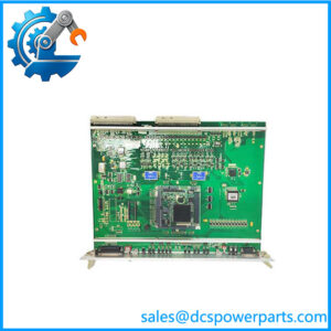
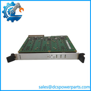
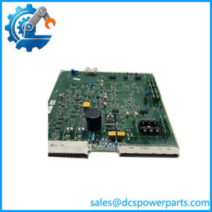
Description
Technical Specifications
| Parameter | Specification |
|---|---|
| Manufacturer | ALSTOM |
| Model | LE109A-1 |
| Product Type | Control Module / Control Board |
| Application | Industrial automation and power-control systems |
| System Integration | ALSTOM proprietary control architecture |
| Signal Processing | System-dependent |
| I/O Configuration | System-dependent |
| Power Supply | Verify from module nameplate/system documentation |
| Communication | Verify exact hardware configuration |
| Mounting | System/chassis dependent |
| Firmware | System-dependent |
| Hardware Revision | Verify from installed unit |
| Operating Temperature | Verify from original ALSTOM documentation |
Product Introduction
The ALSTOM LE109A-1 is a legacy ALSTOM control-system component, but its exact technical identity is difficult to establish from publicly available documentation. Current web sources classify the same part number in several incompatible ways, including an industrial control board, LED status module, auxiliary lockout relay, and traction-control device.
Because these descriptions conflict substantially, the safest engineering classification for ALSTOM LE109A-1 is industrial control module/control board rather than assigning it a specific protection, relay, traction, or DCS function without a matching ALSTOM manual or nameplate.
One secondary technical source describes LE109A-1 as a control module associated with ALSTOM power-control applications and lists configurable digital/analog I/O. However, the same source provides a number of unsupported generic specifications, so those details should not be treated as confirmed.
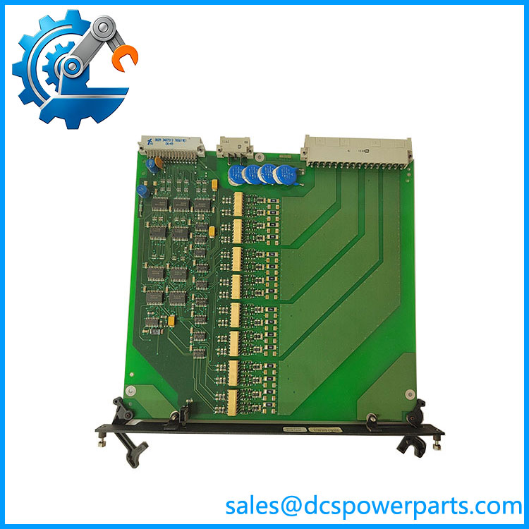
LE109A-1
Main Features & Field Considerations
Legacy ALSTOM integration
The LE109A-1 should be considered system-specific hardware. Physical compatibility alone is not enough to establish functional interchangeability.
Application ambiguity
The available sources disagree on the role of this part. One describes it as a traction motor controller, another as an LED annunciator, and another as a lockout relay. These are fundamentally different products/functions.
Exact identification is critical
For an installed unit, record:
- LE109A-1 marking
- Full nameplate information
- Hardware revision
- Any additional ALSTOM/serial number
- Host system or rack designation
- Connector arrangement
- Installed firmware, if applicable
Do not substitute based on generic descriptions
A replacement should be matched against the original board’s physical layout, connector positions, system slot, and associated documentation.
Replacement Checks
Before replacing an , verify:
- Complete part-number marking
- ALSTOM system/platform
- Rack or chassis position
- Hardware revision
- Connector and backplane arrangement
- Power-supply requirements
- Connected I/O or field circuits
- Firmware/configuration
- Application program
- Existing wiring and terminal assignments
If this module is part of a protection, trip, or safety-related circuit, do not rely on a reseller’s generic functional description when determining interchangeability.
Important Specification Caution
I would not publish claims found on some commercial pages such as 750/1500 VDC traction input, 300 kW motor power, ±1% torque accuracy, SIL 4, 16 LED channels, 500 A/10 kV switching, 220 VAC input, 50 kHz output, or IEC 61850/Modbus support for the . The sources contradict one another and provide no reliable primary documentation tying those specifications to the exact part number.
Procurement Note
For procurement, I recommend using the conservative description:
ALSTOM — Legacy Industrial Control Module / Control Board
If you can provide a photo of the nameplate or PCB, especially the full label and connector side, I can identify the exact ALSTOM function and produce a much more reliable specification table.