Description
Product Overview
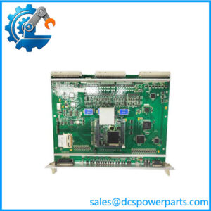
The ALSTOM CMU 42015-115-00 is a legacy control and monitoring module identified as the CMU hardware within the IPS-200 interlocking architecture. This identification is particularly important because recent certification documentation lists MLU 42015-106-00 and CMU 42015-115-00 together as the hardware versions of the IPS-200 interlocking computer. That evidence is considerably stronger than generic online descriptions that simply label the part a “PLC control module.”
Within the documented system architecture, the ALSTOM CMU 42015-115-00 works alongside the MLU rather than being treated as an ordinary analog or digital I/O card. The same certified configuration includes EIOCOM-4 communication hardware, VIIB32S-2 and VIIB32D-2 relay acquisition modules, VOOB16-2 relay-driver modules, and other execution-interface hardware. This makes the CMU relevant to systems where deterministic control and monitoring depend on a defined hardware/software combination.
The ALSTOM CMU 42015-115-00 has also been described by secondary sources as a data/control module for power-system protection and industrial control. However, several commercial listings publish conflicting electrical specifications—115 VAC in some cases, 220 VAC in others, along with unsupported claims about Ethernet/Modbus, CPU speed, memory, and channel counts. Those values should not be copied into an engineering specification without primary documentation. For procurement, the strongest confirmed identification is the CMU 42015-115-00 hardware designation and its documented relationship with MLU 42015-106-00 in the IPS-200 architecture.
Key Technical Specifications
| Parameter | Value |
|---|---|
| Manufacturer | ALSTOM |
| Model | CMU 42015-115-00 |
| Functional Designation | CMU |
| Product Type | Control / Monitoring Unit |
| Associated Platform | IPS-200 safety platform |
| Associated MLU | 42015-106-00 |
| System Function | Control and monitoring |
| Architecture | Modular control/interlocking system |
| Associated Communication Hardware | EIOCOM-4 |
| Associated Acquisition Hardware | VIIB32S-2 / VIIB32D-2 |
| Associated Output Hardware | VOOB16-2 |
| Host/System Interface | System dependent |
| Communication Protocol | Not reliably confirmed for this exact hardware |
| Processor | Not reliably confirmed |
| Memory | Not reliably confirmed |
| Input Channel Count | Not reliably confirmed |
| Output Channel Count | Not reliably confirmed |
| Supply Voltage | Not reliably confirmed |
| Operating Frequency | Not reliably confirmed |
| Operating Temperature | Not reliably confirmed |
| Firmware | System-version dependent |
| Hardware Revision | 42015-115-00 |
| Condition | New Surplus, subject to inspection and functional testing |
The relationship between CMU 42015-115-00 and MLU 42015-106-00 is supported by recent certification documentation for IPS-200/CVC-200T configurations.
Important specification note: Online listings claim values such as 115 VAC, 60 Hz, Ethernet/Modbus-TCP, 8 inputs, 4 outputs, 1 MB memory, and 100 MHz processing. Other listings claim 220 VAC and 50 kHz. These contradictions make those numbers unsuitable as confirmed specifications for the CMU 42015-115-00.
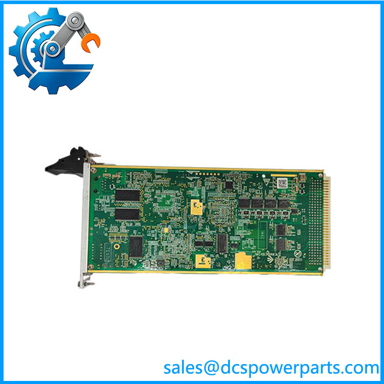
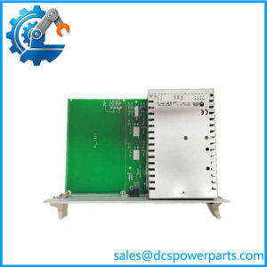
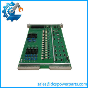
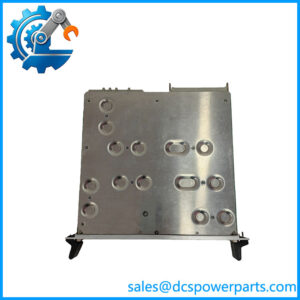
CMU 42015-115-00
Related Products
- ALSTOM MLU 42015-106-00 — The companion Main Logic Unit documented alongside CMU 42015-115-00 in configurations. It should be evaluated together with the CMU when replacing the processing hardware.
- ALSTOM EIOCOM-4 12018-201-01 / 12018-201-50 — Communication-control module used in the documented execution/display subsystem. It provides communication functions rather than the CMU’s central control/monitoring role.
- ALSTOM VIIB32S-2 12019-100-01 / 12019-100-50 — Relay acquisition module for collecting field status information. It operates below the CMU/MLU control layer.
- ALSTOM VIIB32D-2 12019-109-01 / 12019-109-50 — Another relay acquisition module used within the documented execution/display architecture.
- ALSTOM VOOB16-2 12016-102-01 / 12016-102-50 — Relay-driver module that handles output-side field interfaces. It is complementary to CMU rather than an alternative.
- ALSTOM PDDM46-2 12018-100-01 / 12018-100-50 — Turnout-related module in the documented railway interlocking architecture. Its function is application-specific and substantially different from CMU.
- ALSTOM SDDM-2 12019-103-01 / 12019-103-50 — Signal module used for railway signaling interfaces. It belongs to the execution layer rather than the CMU processing layer.
- ALSTOM TCIM-3 12019-105-01 / 12019-105-50 — Track-circuit interface module in the documented architecture. It handles a specialized field interface rather than central control processing.
Frequently Asked Questions
1. What is ALSTOM CMU 42015-115-00 used for?
The strongest available evidence places CMU 42015-115-00 in the architecture, where it is listed as the CMU hardware alongside MLU 42015-106-00.
It should therefore be considered a control/monitoring component of a defined system architecture, not a generic universal PLC CPU.
2. Is CMU 42015-115-00 the same as MLU 42015-106-00?
No.
They are separate hardware units:
- MLU 42015-106-00 — MLU hardware
- CMU 42015-115-00 — CMU hardware
Certification documentation specifically lists both as separate hardware versions within the interlocking computer.
Do not substitute one for the other based on their shared 42015 product-number family.
3. Can I replace CMU 42015-115-00 with a newer controller?
Only if the complete system documentation establishes compatibility.
For a legacy or safety-related system, verify:
- Hardware revision
- MLU compatibility
- System software version
- Backplane/interface requirements
- Communication configuration
- Associated I/O modules
- Approved system configuration
A newer CPU or controller with greater processing capacity does not automatically satisfy the original system’s hardware/software requirements.
4. Can I hot-swap this module?
Do not assume that it can be hot-swapped.
The CMU is part of a central control architecture. Removing it while energized can interrupt system operation and may affect associated safety or interlocking functions.
Unless the exact system documentation explicitly authorizes energized replacement, use the approved shutdown and maintenance procedure.
5. Will I lose my control logic when replacing CMU 42015-115-00?
The answer depends on the specific system architecture and where the application configuration is stored.
Before replacement, preserve:
- System/application configuration
- Software revision
- Hardware revision
- Communication parameters
- MLU/CMU relationship
- I/O configuration
- Diagnostic settings
A replacement CMU that powers up correctly may still be unsuitable if its system configuration does not match the installed application.
6. Does CMU 42015-115-00 support Ethernet or Modbus/TCP?
Some secondary listings claim Ethernet/Modbus-TCP, while others provide entirely different interface descriptions.
I would not specify Ethernet or Modbus/TCP as a confirmed feature for procurement without the applicable ALSTOM system documentation. The certified documentation establishes the presence of EIOCOM-4 as separate communication-control hardware, which is another reason not to assume that CMU itself provides a standard Ethernet port.
7. How should I verify a New Surplus CMU 42015-115-00?
For a control module with a defined system role, inspect and test the unit before deployment:
- Confirm CMU 42015-115-00 marking.
- Record PCB and hardware revision.
- Inspect connectors and backplane contacts.
- Check for corrosion, contamination, or storage damage.
- Verify compatibility with MLU 42015-106-00.
- Confirm system software/firmware revision.
- Perform controlled power-up.
- Run available diagnostics.
- Verify communication with associated modules.
- Confirm I/O exchange through the complete system.
- Perform application-level testing before returning the equipment to service.
Procurement judgment: The most credible current evidence identifies CMU 42015-115-00 as the CMU hardware used with MLU 42015-106-00 in the platform, rather than supporting the generic 115 VAC/100 MHz/1 MB specifications repeated by several commercial listings. For a critical replacement, use the exact hardware designation, system version, and companion-module configuration as the acceptance criteria.