Description
Key Technical Specifications
| Parameter | Value |
|---|---|
| Manufacturer | ABB |
| Model | TVOC-2-240 |
| Order Number | 1SFA664001R1001 |
| Product Type | Arc Monitor / Arc Flash Protection Relay |
| Series | Arc Guard System™ TVOC-2 |
| Supply Voltage | 100–240 VAC, 50/60 Hz; 100–250 VDC |
| Power Consumption | Approx. 5 W |
| Detector Inputs | 10 optical detector inputs |
| Expandable Inputs | Up to 30 optical detectors with extension modules |
| Trip Outputs | Solid-state trip contacts |
| Auxiliary Contacts | Relay indication outputs |
| Communication | Modbus RTU available through system configuration |
| Mounting | Panel / switchgear cabinet mounting |
| Protection Degree | IP54 front side (with appropriate installation) |
| Operating Temperature | -25°C to +55°C |
| Dimensions (W×H×D) | Approx. 210 × 230 × 80 mm |
| Application | LV/MV switchgear arc flash protection |
Product Introduction
ABB TVOC-2-240 1SFA664001R1001 Overview
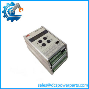
The ABB TVOC-2-240 1SFA664001R1001 is the main arc monitoring unit of the ABB Arc Guard System™ TVOC-2 family. It is designed to detect the intense optical emission generated during an electrical arc fault and rapidly transmit a trip signal to associated circuit breakers or protection devices. By reducing the time an arc remains active, the system helps limit damage to switchgear and connected equipment.
The ABB TVOC-2-240 1SFA664001R1001 is installed in electrical distribution systems where arc flash protection is required, including industrial switchgear assemblies, motor control centers, and power distribution panels. The unit receives signals from optical arc sensors installed throughout the cabinet and processes these inputs to determine whether an arc event has occurred.
The ABB TVOC-2-240 includes ten detector inputs and can be expanded through additional detector modules to cover larger switchgear arrangements. It also includes an HMI interface that can be mounted externally on the cabinet door for easier status monitoring and operation.
The ABB -240 1SFA664001R1001 is commonly applied in power generation facilities, manufacturing plants, oil and gas installations, and other industrial environments where electrical switchgear reliability is critical. Replacement requires verification of detector layout, breaker trip wiring, auxiliary contacts, supply voltage, and existing protection scheme configuration.
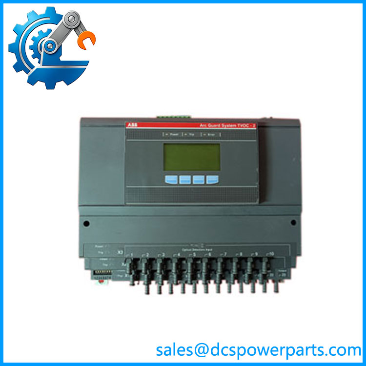
TVOC-2-240
Application Scenarios & Field Pitfalls (The Engineer’s Perspective)
Engineering Pain Point
An arc protection system shows detector faults, unexpected alarms, or fails to issue a trip command during testing. The arc monitor may appear to be the problem, but the complete protection chain should be checked.
The troubleshooting path should include:
- Optical sensor condition
- Fiber/optical cable routing
- Detector input status
- Trip circuit wiring
- Breaker interface
- Power supply stability
- System configuration
The is only one part of the arc protection system. Sensor placement, wiring, and breaker trip circuits are equally important.
Typical Applications
Low Voltage Switchgear
Used for:
- Motor control centers
- Distribution panels
- Industrial electrical cabinets
Medium Voltage Switchgear
Applied in:
- Substation equipment
- Plant power distribution systems
- Generator switchgear
Process Industries
Used in:
- Chemical plants
- Refineries
- Continuous production facilities
Power Generation
Applied for:
- Generator protection systems
- Auxiliary switchgear protection
- Plant electrical distribution equipment
Technical Pitfalls to Avoid
1. Verify Detector Configuration
Before replacement, confirm:
- Number of installed optical sensors
- Detector input assignment
- Sensor cable length
- Cabinet coverage arrangement
A new monitor must match the existing sensor network.
2. Check Breaker Trip Interface
Verify:
- Trip relay wiring
- Breaker input requirements
- Solid-state output compatibility
- Protection coordination settings
A functioning arc monitor cannot protect the system if the breaker trip path is incorrect.
3. Confirm Supply Voltage
The version supports a specific voltage range. Confirm:
- AC/DC supply type
- Existing control voltage
- Terminal wiring
Installing the wrong voltage variant can cause startup or reliability issues.
4. Test the Complete Protection System
Recommended checks:
- Optical detector test
- Trip output verification
- Alarm indication test
- HMI operation check
Arc protection equipment should be validated as a complete safety function, not only as an individual hardware replacement.
Related Products
- Optical input extension module for additional arc detector connections.
- Extension module designed for longer detector cable applications.
- Additional HMI unit for remote cabinet door mounting.
- ABB -DP Series
Optical detector cables available in multiple lengths. - ABB CSU-2 Current Sensing Unit
Current verification module used with systems where light and current detection are combined. - ABB Arc Guard System™
Complete optical arc flash protection platform for industrial switchgear applications.